


8 C1570M-C (5/06)
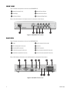
FRONT VIEW
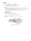
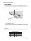
Figure 1 illustrates the components on the front of the CM9700MDD-EVS.
Refer to Front Panel Indicators in the Operation section for a description of each indicator.
Figure 1. CM9700MDD-EVS Front View
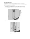
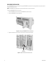
REAR VIEW
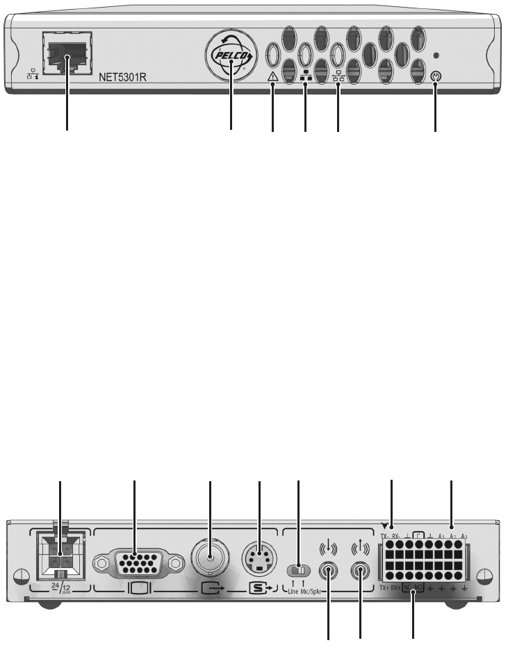
Figure 2 illustrates the components on the rear of the CM9700MDD-EVS.
Refer to Basic Hardware Connections in the Installation section for a description of the connectors.
Figure 2. CM9700MDD-EVS Rear View
ᕡ Network Connector (RJ-45) ᕤ Network Status Indicator
ᕢ Pelco Badge ᕥ Network Activity Indicator
ᕣ Unit Status Indicator ᕦ Configuration/Reset Button
ᕡ Power ᕦ Audio In (reserved for future use)
ᕢ VGA Out (Reserved for future use) ᕧ Audio Out
ᕣ Video Out (MXB connection) ᕨ RS-422 Connectors
ᕤ S-Video Out (reserved for future use) ᕩ Relay Connectors (reserved for future use)
ᕥ Audio Switch (reserved for future use) ᕫᕾ Alarm Connectors (reserved for future use)
ᕡ
ᕢ
ᕣ
ᕤ
ᕥ
ᕦ
ᕡᕢᕣᕤᕥ ᕨᕫᕾ
ᕦᕧ ᕩ