


Step 1: Check the Installation Kit 5
Step 1
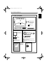
Type 150/400
Autopilot
System
Installation
Guide
Worldwide
Distributors
!
D5377-1
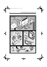
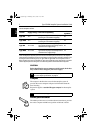
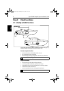
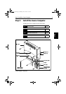
Course computer
Course computer components
Core pack – parts supplied
Ferrite
(for power cable)
Cable clamp Tie-wrap (for cable clamp)
No8 x 3/4 inch pan-head
self-tapping screws (x5):
• 2 for course computer
• 3 for cable clamp
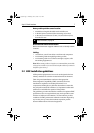
No8 x 3/4 inch pan-head self-tapping screws (x3)
for rudder position sensor
No8 x 3/4 inch countersunk self-tapping screws (x2)
for tiller pin
No8 x 3/4 inch pan-head
self-tapping screws (x4)
Compass
warning label
Installation Guide
(includes warranty
documents and
fitting templates)
Worldwide
Distributor List
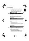
Fluxgate compass
with 8 m (26 ft) cable
Compass components Rudder position sensor components
Rudder position sensor
with 10 m (32 ft) cable
Connecting rod (M6), nuts (M6 x2)
and ball-pin sockets (x2)
Tiller pin
Note: This illustration shows the parts supplied with Type 150, 150G, 400 and 400G autopilot core packs.
81173_3.book Page 5 Thursday, June 7, 2001 11:51 AM