


Step 5: Install the Rudder Position Sensor 23
Step 5
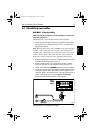
Ensuring correct alignment
CAUTION:
Take care to ensure correct rudder sensor alignment. If the
sensor is not correctly aligned, the autopilot system will not
perform accurately.
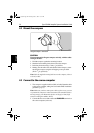
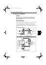
Vertical alignment
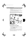
When viewed from the front of the boat, the connecting rod should:
• be as level as possible, so the ball-joints at each end are level
• remain parallel to the tiller arm’s plane of rotation at all times
Note: If misalignment exceeds +/-5° the ball-joints will bind or fail.
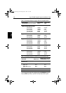
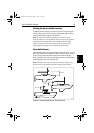
Maximum
permitted
travel: +/- 60˚
Cable entry
Parallel
Minimum: 75 mm (3 in)
Maximum: 310 mm (12 in)
90˚
60˚ 60˚
Min: 101 mm (4 in)
Optimum: 140 mm (5.5 in)
Max: 190 mm (7.5 in)
D5387-1
Mounting base
Tiller arm
or quadrant
Rudder position
sensor
Connecting rod
Ball joints (level)
Sensor arm
Parallel
Front view - rudder amidships
Top view - rudder amidships
Aft
81173_3.book Page 23 Thursday, June 7, 2001 11:51 AM