


42 Type 150/400 Autopilot System: Installation Guide
Step 9
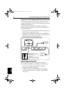
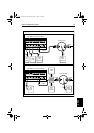
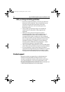
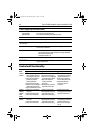
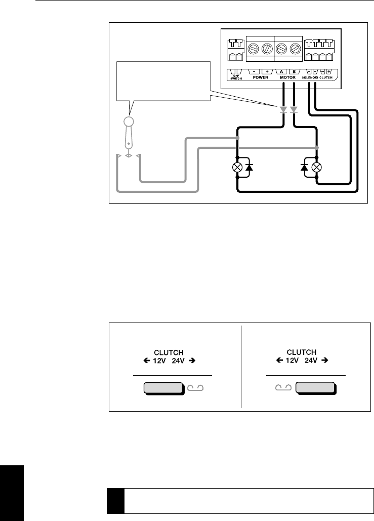
Selecting clutch voltage (Type 400/400G)
Note: All Raymarine 12 V and 24 V drive units with a clutch have a
12 V clutch so you do NOT need to re-position the clutch fuse.
You can use the Type 400/400G course computers with other
manufacturers’ drives that have either 12 V or 24 V clutches.
Select the appropriate clutch voltage by positioning the clutch fuse to
the left (12 V clutch) or right (24 V clutch).
9.4 Setting-up the autopilot
When you have installed and connected all components, you need to
check the system and then set-up the autopilot.
Í
For more information about autopilot set-up, refer to the control unit
owner’s handbook.
12 V
24 V
D5397-1
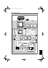
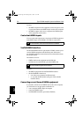
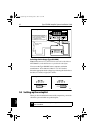
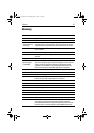
Spool valves
(diodes across
spool valves)
Course computer connections
Return cables
Diodes
Electronic steering
or jog lever
If electronic steering or jog lever
is used on the same solenoids, fit
diodes (suggested type: 1N4004)
as indicated to prevent
backfeeding the course computer.
4
4
D5398-1
Fuse position: 12 V clutch Fuse position: 24 V clutch
81173_3.book Page 42 Thursday, June 7, 2001 11:51 AM