


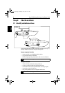

Step 2: Check Locations 7
Step 2
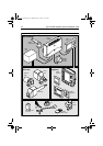
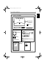
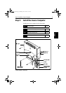
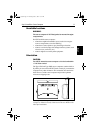
Rotary rudder position sensor location:
• suitable base alongside the rudder stock and tiller arm.
• so the ball-joints at each end of the connecting rod are level
• so the sensor arm is between 75 mm (3 in) and 310 mm (12 in)
from the tiller arm
Drive unit and control unit locations
Refer to the information supplied with these units to identify suitable
locations.
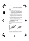
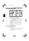
Cabling:
• consider how you will run cables to and from each component
• avoid running cables through bilges where possible
• avoid running cables close to fluorescent lights, engines, radio
transmitting equipment etc.
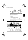
Note: When cutting cables to length, we recommend that you include
a loop of extra cable so you can cut and strip the cables a few times in
the future (if necessary).
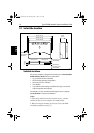
2.2 EMC installation guidelines
All Raymarine equipment and accessories are designed to the best
industry standards for use in the recreational marine environment.
Their design and manufacture conforms to the appropriate
Electromagnetic Compatibility (EMC) standards, but correct
installation is required to ensure that performance is not
compromised. Although every effort has been taken to ensure that
they will perform under all conditions, it is important to understand
what factors could affect the operation of the product.
The guidelines given here describe the conditions for optimum EMC
performance, but it is recognized that it may not be possible to meet
all of these conditions in all situations. To ensure the best possible
conditions for EMC performance within the constraints imposed by
any location, always ensure the maximum separation possible
between different items of electrical equipment.
Í
For more information, see page 23
81173_3.book Page 7 Thursday, June 7, 2001 11:51 AM