


GPS chartplotters Page 17
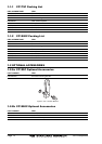
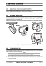
2.3.0 Flush Mounting
NOTE
Before drilling holes, it is recommended the GPS antenna be positioned where the location is
planned to be drilled, cable connected to the Plotter and the GPS chartplotter turned on to ensure
a GPS FIX is received.
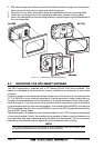
1. Remove the threaded base from the GPS antenna dome.
2. To ease installation a flush mounting template for the antenna has been included.
3. Apply the mounting template sticker to the area that was verified for GPS reception.
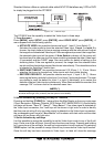
4. Then, drill out the 0.63” (16mm) and 0.16” (4mm) holes, and remove the template.
5. Insert the cable into the 0.63” (16mm) hole and route to the GPS chartplotter.
6. Apply a small amount or RTV to the under side of the antenna.
7. Place the antenna and then screw it into place using the screws. In some cases the
screw may not be long enough, if this happens simply apply more RTV to the underside
of the antenna to glue it into place.
Figure 2.3.0 - Installing the GPS Smart antenna
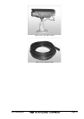
Figure 2.3.0 - Installing the GPS Smart antenna (Flush)
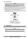
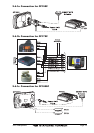
2.4 CONNECTIONS
The GPS chartplotter has a cable or connectors that are used to connect the chartplotter
to Power Supply, to the GPS smart antenna, optional FF520 Black Box Fish Finder and to
NMEA devices such as VHF’s, digital instruments and autopilots.
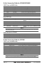
NOTE
The GPS chartplotter can send many sentences to external NMEA devices. The NMEA output
wires are Brown and White. If you have connected devices as shown in the below table and need
to feed NMEA to other devices (Autopilot RADAR…) you can parallel wires from the Brown or White
wires.