


Page 18 GPS chartplotters
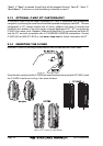
2.4.0a Connection Table for CP155C/CP1000C
12VDC Power and NMEA Cable
Pin Wire Color Description Connection Example
1 Black Battery Ground Connect to battery ground and Black wire of GPS Antenna
2 Red Battery Positive Connect to Battery Positive and Red wire of GPS Antenna
3 Green NMEA Common Common for NMEA devices
4 Blue VHF Input Conncect to VHF with DSC and DSE output
5 Brown VHF output Connect to VHF to supply GPS position data
6 Gray Fishfinder Input Standard Horizon Fishfinder, see FF520 owner's manual
7 White Fish Finder Output Standard Horizon Fishfinder, see FF520 owner's manual
8 Yellow GPS Antenna Input Connect to GPS Antenna Green wire
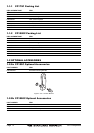
Smart GPS Cable
Pin Wire Color Description Connection Example
1 Red Battery Positive Connect to Battery Positive and Red wire of GPS
Antenna
2 Green Smart GPS NMEA Input Connect to Smart GPS Input
3 Brown Smart GPS NMEA Output Connect to Smart GPS Output
4NC
5NC
6 Black/Yellow Battery Ground Connect to battery ground and Black wire of GPS
Antenna
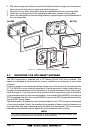
NOTE
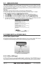
The CP155C and CP1000C have connectors on the rear panel that allow the GPS Smart antenna
to be directly connected.
Video Connector for CP1000C
Pin Description Connection Example
1 Ground Connect to Video Signal Ground of DVD/VCR/Video Cameras
2 + 9 / 12 VDC Connect to Video Cameras Power Input
3 Video Signal + Connect to Video Signal + of DVD/VCR/Video Cameras
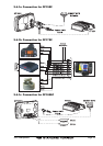
2.4.0b Connection Table for CP175C
12VDC Power and NMEA Cable
Wire Color Description Connection Example
Black Battery Ground Connect to battery ground and Black wire of GPS Antenna
Red Battery Positive Connect to Battery Positive and Red wire of GPS Antenna
Green NMEA Common Common for NMEA devices
Blue VHF Input Conncect to VHF with DSC and DSE output
Brown VHF output Connect to VHF to supply GPS position data
Gray Fish Finder Input Standard Horizon Fish Finder, see FF520 owner's manual
White Fish Finder Output Standard Horizon Fish Finder, see FF520 owner's manual
Yellow GPS Antenna Input Connect to GPS Antenna Green wire
Pink GPS Antenna Output Connect to GPS Antenna Brown wire
Orange Not used No connection
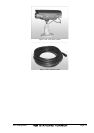
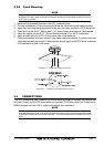
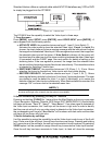
NOTE
For the CP175C the GPS Smart antenna should be wired according to the below diagram.