


Page 34 Portable Hot Oil Temperature Control Units
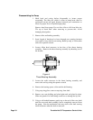
Disassembling the Pump
1. Mark head and casing before disassembly to insure proper
reassembly. The idler pin, which is offset in pump head, must be
positioned toward and equal distance between port connections to
allow for proper flow of liquid through pump.
Remove head from pump. Do not allow idler to fall from idler pin.
Tilt top of head back when removing to prevent this. Avoid
damaging head gasket.
2. Remove idler and bushing assembly.
3. Insert length of hardwood or brass through port opening between
rotor teeth to keep shaft from turning. Bend up tang of lockwasher
and with a spanner wrench.
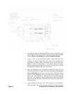
4. Loosen Allen head setscrews in the face of the thrust bearing
assembly. Remove the thrust bearing assembly by threading out of
the bracket.
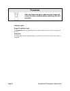
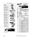
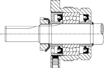
Figure 4
Thrust Bearing Assembly
5. Loosen the radial setscrews in the thrust bearing assembly and
remove the end cap using the spanner wrench.
6. Remove the bearing spacer collars and the ball bearing.
7. Using snap ring pliers, remove snap ring from shaft.
8. Remove two nuts holding seal gland plate and seal gland in place.
Slide seal gland off of shaft being careful not to damage the lip seal.
9. Using a soft headed hammer, gently tap on the end of the rotor shaft
until the rotor and shaft assembly can be completely removed from
the pump. Note the mechanical seal may stick to the shaft causing
initial resistance when the shaft is removed.