


Page 36 Portable Hot Oil Temperature Control Units
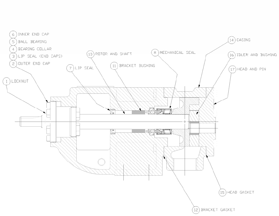
3. Coat idler pin with non-detergent SAE 30 weight oil and place idler
and bushing on idler pin in head. If replacing with carbon graphite
bushing, Refer to Installation of Carbon Graphite Bushings.
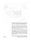
4. Using a .010 to .015 inch head gasket, install head and idler
assembly on pump. Pump head and casing were marked before
disassembly to insure proper reassembly. If not, be sure idler pin,
which is offset in pump head, is positioned toward and equal
distance between port connections to allow for proper flow of liquid
through pump. Tighten head capscrews evenly.
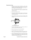
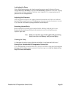
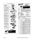
5. Place the mechanical seal installation tapered half rings over the
shaft and apply P-80 oil supplied with the replacement seal, grease is
not recommended on the sleeve and rotor shaft. Slide the rotating
portion of the mechanical seal on the shaft until it bottoms on the
shaft step. See FIGURE 4. Remove the seal installation tapered
half rings. It is important when using the rings to make sure the thin
edge is facing the direction of the shaft end, and that the thick end is
facing the rotor.
6. Apply lubricant to the seal seat o-ring and push it in the bracket.
Note the shinny side of the seat goes towards the carbon graphite