


Portable Hot Oil Temperature Control Units Page 37
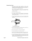
seal face.
7. Apply Dow Corning #44 high temperature silicon grease to the lip
seal area in the seal gland and install on the shaft. Install the seal
gland plate and secure with two nuts.
8. Pack ball bearing with Dow Corning #44 high temperature silicon
grease and install in the thrust bearing housing. Place bearing spacer
collars inside the lip seals. Thread the end cap into the bearing
housing and tighten with a spanner wrench. Tighten the radial set
screws that lock the end cap in place.
9. Using the snap ring pliers, install the snap ring onto the shaft.
10 Thread the thrust bearing assembly into the bracket. Turn in until
hand tight. This forces the rotor against the head.
11. Put lockwasher and locknut on shaft. Insert length of hardwood or
brass through port opening between rotor teeth to keep shaft from
turning. Tighten locknut to 50 – 70 ft.-lbs. torque and bend one tang
of lockwasher into slot.
12. Adjust pump end clearance. Refer to section on Thrust Bearing
Adjustment.
13. Lubricate all grease fittings with Dow Corning #44 high
temperature silicon grease.
Thrust Bearing Adjustment
1. Loosen axial setscrews in face of end cap on the thrust bearing
assembly. If rotor shaft cannot be turned by hand, back off the
thrust bearing assembly until there is a noticeable drag of the shaft.
Note mechanical seal will provide some drag and this is a normal
condition. The thrust bearing assembly must be turned in until it can
just be turned over by hand. This ensures the rotor is against the
head and a zero end clearance condition exists.
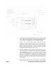
2. Make a mark on the OD of the bearing housing and a corresponding
mark on the bracket. Back off thrust bearing housing the required
number of marks or distance on the OD as shown below.
3. Tighten the axial setscrews in the face of the thrust bearing
assembly. Make sure the rotor shaft turns freely. If it does not,
repeat steps 1 and 2.
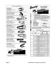
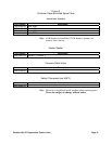
PUMP
SIZE
Turn Outer End Cap C.C.W.
No. of Notches*
or Length on O.D., Inches
G
-
0.75"
HL, HV
6
1"
KK
10
1.38"