


5-12
SUPERSERVER 6025B-3/6025B-3R User's Manual
5-8 Connector Defi nitions
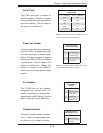
Power LED
The Power LED connection is located
on pins 15 and 16 of JF1. Refer to the
table on the right for pin defi nitions.
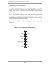
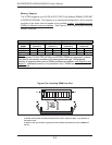
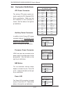
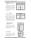
ATX Power Connector
The primary ATX power supply con-
nector meets the SSI (Superset ATX)
24-pin specifi cation. Make sure that
the orientation of the connector is
correct. See the table on the right for
pin defi nitions.
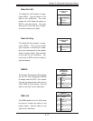
NMI Button
The non-maskable interrupt button
header is located on pins 19 and 20
of JF1. Refer to the table on the right
for pin defi nitions.
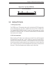
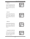
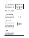
Auxiliary Power Connector
In addition to the Primary ATX power
connector (above), the Auxiliary 4-pin
connector at JPW2 must also be con-
nected to your power supply. See the
table on the right for pin defi nitions.
NMI Button
Pin Defi nitions (JF1)
Pin# Defi nition
19 Control
20 Ground
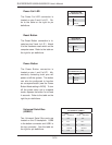
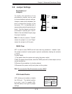
Processor Power
Pin Defi nitions (JPW3)
Pins Defi nition
1 through 4 Ground
5 through 8 +12V
+12V 4-pin Aux. Power
Pin Defi nitions (JPW2)
Pins Defi nition
1 & 2 Ground
3 & 4 +12V
Power LED
Pin Defi nitions (JF1)
Pin# Defi nition
15 Vcc
16 Control
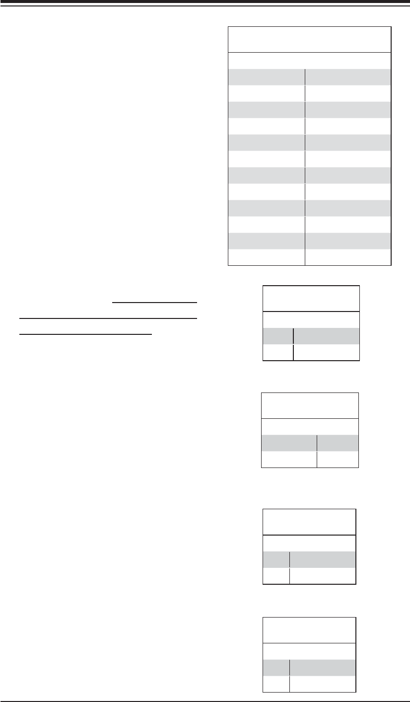
ATX Power 24-pin Connector
Pin Defi nitions (JPW1)
Pin# Defi nition Pin # Defi nition
13 +3.3V 1 +3.3V
14 -12V 2 +3.3V
15 COM 3 COM
16 PS_ON 4 +5V
17 COM 5 COM
18 COM 6 +5V
19 COM 7 COM
20 Res (NC) 8 PWR_OK
21 +5V 9 5VSB
22 +5V 10 +12V
23 +5V 11 +12V
24 COM 12 +3.3V
Processor Power Connector
JPW3 must also be connected to the
power supply to provide power for the
processor(s). See the table on the
right for pin defi nitions.