


6-2
SUPERSERVER 6025B-3/6025B-3R User's Manual
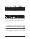
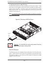
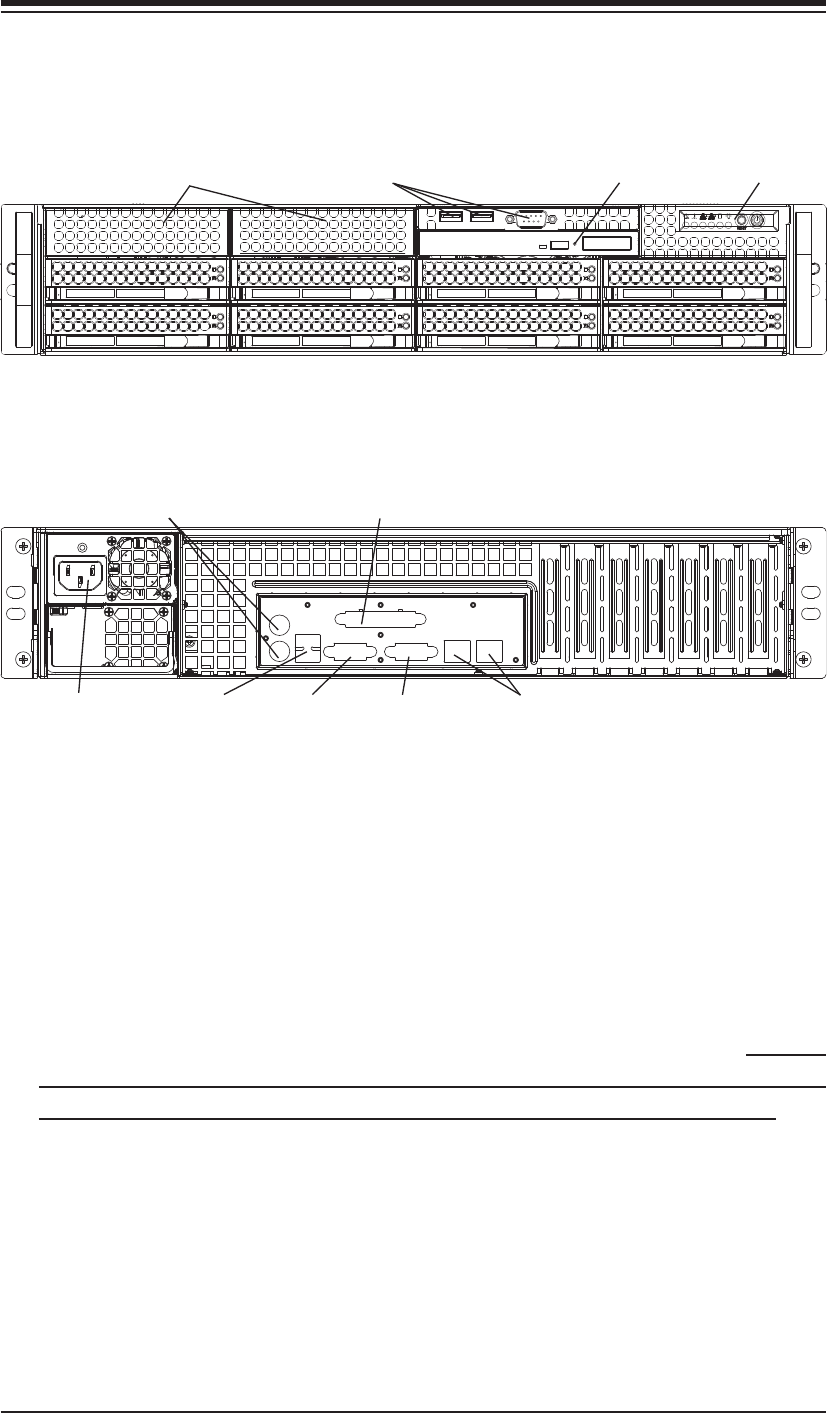
Figure 6-1. Front and Rear Chassis Views
6-2 Control Panel
The control panel (located on the front of the chassis) must be connected to the
JF1 connector on the serverboard to provide you with system status indications. A
ribbon cable has bundled these wires together to simplify the connection. Connect
the cable from JF1 on the serverboard to JP4 on the Control Panel PCB (printed
circuit board). Make sure the red wire plugs into pin 1 on both JF1 and JP4. Pull
all excess cabling out of the airfl ow path. The LEDs inform you of system status.
See Chapter 3 for details on the LEDs and the control panel buttons. Details on
JF1 can be found in Chapter 5.
Control Panel
Slim DVD-ROM Drive
USB/COM Ports
SAS Drives (8)
Ethernet Ports USB Ports
Keyboard/Mouse Ports
COM1 Port
7 Low-Profi le PCI Slots
VGA Port
Parallel Port
Power Supply*
*Note: the lower (bottom) power supply module is a dummy on the 6025B-3. On the 6025B-3R, a redun-
dant power supply module is located here.
3.5" Drive Bays