


25
APPENDIX III: SA INVERTER OPTIONS
GENERAL
The SA41 employs a rear chassis-mounted 25-pin connector, which allows you to add a selection of
optional features to your power system. Note that the software for these functions is already
installed within the SA41 microcontroller.
The full range of features are:
(a) Remote Keypad: A low profile keypad with 2-line Liquid Crystal Display, which can
be located up to 500 metres from your SA41.
Wiring requirements - 6 conductor shielded cable.
(b) DC Current Shunt: Consists of a 200 Amp 75mV current shunt, mounted on an insulated
base, and a twin flex loom for current sensing.
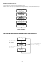
(c) Controller Outputs: Two external relay or contactor coils can be energised for various AC
or DC switching applications.
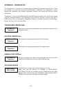
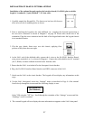
(d) Alarm Inputs: Two digital inputs that can be programmed to monitor switch contact
status or voltage levels (refer to following circuits for examples)
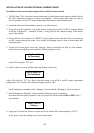
SA-SB-01 INTERFACE KIT
The Interface Kit SA-SB-01 plugs into the rear of the SA41 and provides a convenient termination
point for the various options outlined above. The screw terminals are numbered from 1 to 14 and
the connections are as follows:
TERMINAL NO DESCRIPTION
1 & 14 +48V with 1A internal fuse
2 Alarm input 2
3 Alarm input 1
4 0V
5 - 8 Keypad data lines
9 Keypad +12V
10 & 11 200A current shunt connections
12 Controller output 2
13 Controller output 1
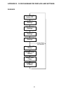
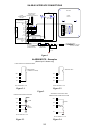
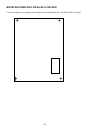
Please refer also to Diagram 1 overleaf.