


Installation
3–16 975-0263-01-01
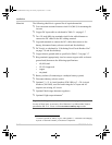
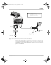
A separate screw is provided to connect the AC input ground (see
Figure 3-5 on page 3–16).
8. Strip about 2 inches (50 mm) from the jacket of the AC input cable.
The AC input cable may be either solid or stranded, but must have
three conductors and be sized as in Table 3-3 on page 3–14. (The AC
terminal block accepts wire sizes up to No. 10 AWG.)
9. Strip approximately 3/8 inch (10 mm) off the insulation of each
conductor.
10. Run the AC cable through the right-hand side strain-relief clamp and
into the wiring compartment.
11. Fasten the Ground wire to the grounding screw.
12. Using the 1/8 inch slot screwdriver, loosen the wire attachment
screws on the terminals.
13. Insert the Line and Neutral wires into the corresponding terminals.
14. Tighten the wire attachment screws to a torque of 1.3–1.8 lbf-ft
(1.76–2.44 Nm). Leave some wiring slack inside the wiring
compartment.
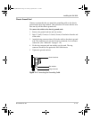
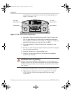
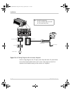
Figure 3-5
XM 1800 AC Wiring Compartment
Select
Utilit y
Battery
Fault
STATUS
XM1000
Input Voltage( V)
Input Current (A)
Output Power (W)
AC
IN
AC
OUT
GND GND
CAUTION!
Do not connect the AC OUT to any other
source of power.Damage to unit may occur.
NL LN
AC knockout
AC input
ground screw
AC output
ground screw
AC knockout
CAUTION: Reverse polarity
Improper connections (connecting a line conductor to a neutral conductor, for
example) will cause the XM 1800 to malfunction and may permanently damage
the inverter. Damage caused by a reverse polarity connection is not covered by
your warranty.
Xantrex_PRO1800.book Page 16 Tuesday, April 24, 2007 11:33 AM