Installation, cont’d
MTPX Plus Twisted Pair Matrix Switchers • Installation
2-8
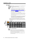
By default, the audio ties follow the video ties. Audio breakaway, which can
be activated via the front panel or under serial port or Ethernet control, allows
you to select from any one of the audio input sources and route it separately
from its corresponding video source. See chapter 3, “Operation”, chapter 4,
“Programmer’sGuide”,chapter5,“MatrixSoftware”,andchapter6,
“HTML Operation”, for details.
RS-232/RS-422 connection
i
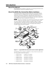
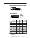
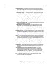
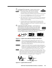
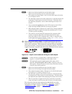
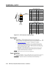
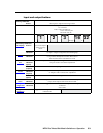
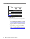
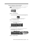
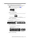
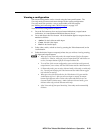
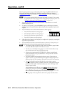
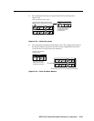
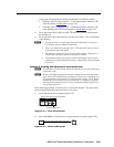
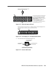
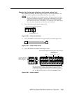
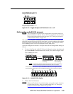
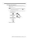
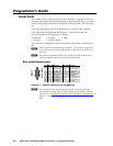
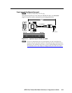
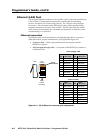
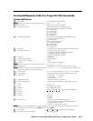
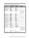
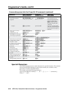
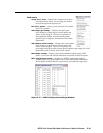
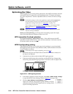
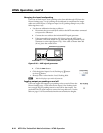
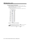
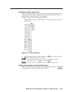
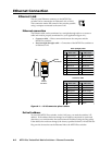
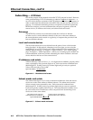
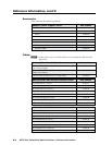
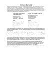
Remote RS-232/RS-422 connector — Connect a host device, such as a
computer, touch panel control, or RS-232 capable PDA to the switcher via this
9-pin D connector for serial RS-232/RS-422 control (figure 2-9).
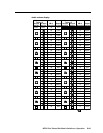
RS-232 Function Pin Function
1
2
3
4
5
6
7
8
9
—
TX
RX
—
Gnd
—
—
—
—
Not used
Transmit data
Receive data
Not used
Signal ground
Not used
Not used
Not used
Not used
—
TX–
RX–
—
Gnd
—
RX+
TX+
—
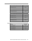
Not used
Transmit data (–)
Receive data (–)
Not used
Signal ground
Not used
Receive data (+)
Transmit data (+)
Not used
RS-422
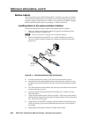
5
1
9
6
RS232/RS422
REMOTE
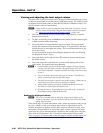
Figure 2-9 — Remote RS-232/RS-422 connector
See chapter 4, “Programmer’s Guide”, for definitions of the SIS commands
(serial commands to control the switcher via this connector) and chapter 5,
“Matrix Software”, for details on how to install and use the control software.
N
TheswitchercansupporteithertheRS-232orRS-422serialcommunication
protocol,andcanoperateat9600,19200,38400,or115200baudrates.
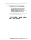
See“SelectingtherearpanelRemoteportprotocolandbaudrate”onpage3-50,
toconguretheRS-232/RS-422portfromthefrontpanel.
If desired, connect an MKP 2000 or MKP 3000 remote control panel to the
switcher’s RS-232/RS-422 connector. Refer to the MKP2000RemoteControl
PanelUser’sManual or the MKP3000User’sManual for details.
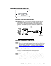
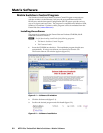
Ethernet connection
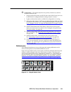
j
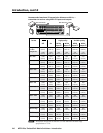
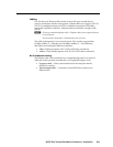
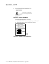
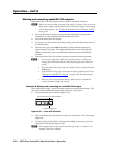
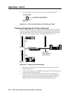
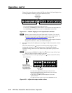
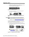
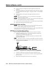
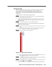
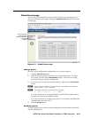
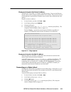
LAN port — If desired, for IP control of the matrix switcher, connect the
switcher to a PC or to an Ethernet LAN via this RJ-45 connector.
You can use a PC to control the networked switcher with SIS
commands from anywhere in the world. You can also control
the switcher from a PC that is running Extron’s Windows-based
control program or has downloaded HTML pages from the
switcher.
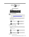
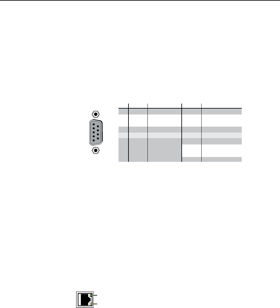
Ethernet connection indicators — The Link and Activity LEDs
indicate the status of the Ethernet connection. The Link LED
indicates that the switcher is properly connected to an Ethernet
LAN. This LED should light steadily. The Activity LED
indicates transmission of data packets on the RJ-45 connector.
This LED should flicker as the switcher communicates.