


CMX High Performance Material & Coating Thickness Gauge
29
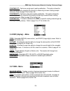
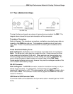
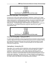
3.17 Top & Bottom End Caps
The top & bottom end panels are where all connections are made to the CMX. The
diagram above shows the layout and description of the connectors:
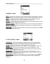
Transducer Connectors
Refer to Diagram: The transducer connectors, and battery cover/probe zero disk are
located on the CMX’s top end cap. The transducer connectors are of type Lemo
“00”. Note: There is no polarity associated with connecting the transducer to the
CMX.
Probe Zero Disk & Battery Cover
Refer to Diagram: The Battery cover is the large round disk shown in the diagram.
Note: This same disk is also used as a probe zero disk. Simply remove the cover
when replacing the batteries (3 AA cells). When performing a manual probe zero
function, simply place the transducer on disk making firm contact. Important: Be
sure to follow the polarity labels located on the back label of the CMX. Note:
Rechargeable batteries can be used, however they must be recharged outside of the
unit in a stand alone battery charger.
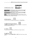
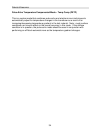
RS-232 Connector
Refer to Diagram: The RS-232 connector, located on the bottom end cap, is a 2 pin
female Lemo connector. It is designed to connect directly from the CMX to a
standard AT serial port on a PC. The cable supplied with the CMX is a Lemo to 9 pin
serial cable. Note: This connector is also used to upgrade the CMX with the latest
version of firmware.
USB Serial to USB Converter Cable
A converter cable can be attached to the 9 pin serial cable in needed (part no. N-402-
0510).