


Dakota Ultrasonics
76
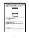
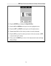
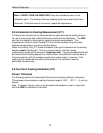
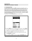
Note: CHECK YOUR CALIBRATION! Place the transducer back on the
calibration point. The coating thickness reading should now match the known
thickness. If the thickness is not correct, repeat the steps above.
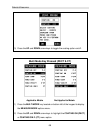
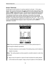
9.5 Introduction to Coating Measurement (CT)
In the previous sections we’ve discussed how to setup and use the coating feature
for use in conjunction with material thickness and flaw and pit detection. The CMX
also has the capability to be used for general coating measurements. This
measurement mode is called Coating (CT) and can be enabled using the same
methods as described in a previous section above.
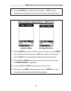
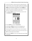
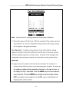
When the Coating Only (CT) mode is enabled, a two point calibration on the coating
samples must be performed. This is to ensure linearity over the coating
measurement range will be achieved. Important note: If coating measurements will
be made with the coating applied to a metal surface, the calibration must be done in
the same manner, with the samples coupled to a metal surface. However, if the
coating will be measured as a stand alone material, the calibration must be
performed the same way.
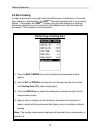
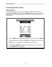
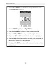
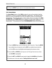
9.6 Two Point Coating Calibration (CT)
Known Thickness
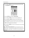
The following section will demonstrate the two point coating calibration procedure.
This example demonstrates a coating thickness range of .040” - .120” ( 1 – 3 mm) as
follows:
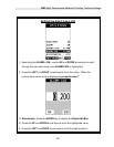
Note: It’s always handy to carry a set of mechanical calipers to use in conjunction
with the CMX for calibration in the field: