


CMX High Performance Material & Coating Thickness Gauge
57
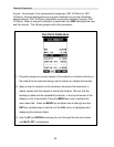
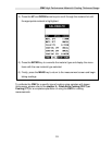
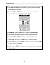
the user would see is a black screen from 0.00” – 1.00” with no view of the bottom
contour at 1.75”.
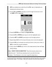
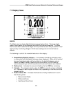
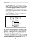
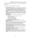
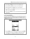
The following is a list of the viewable features on the display:
A. Repeatability/Stability Indicator – This indicator should be commonly used
in conjunction with the digital thickness values displayed. When all the vertical
bars are fully illuminated and the last digit on the digital thickness value is
stable, the CMX is reliably measuring the same value 3 to 200 times per
second, depending on which measurement mode and features are enabled.
B. Battery Icon – Indicates the amount of battery life the CMX has remaining.
C. Velocity – The material velocity value the CMX is currently using or calibrated
for. Displayed in either English or Metric units, depending on the what units
the gauge is set for.
D. Feature Status Bar – Indicates the features currently enabled and in use in
the following order:
• Measurement Mode (P-E, PECT, PETP, E-E, COAT)
• Differential Mode (ON/OFF)
• High Speed Scan Mode (ON/OFF)
• Alarm Mode (ON/OFF/AUDIBLE)
• Gain Setting (VLOW, LOW, MED, HI, VHI)
E. Digital Material Thickness Value – Smaller font size when the B-Scan
display view is enabled.
F. Scan Bar – Another view of material thickness in a deflection style horizontal
bar. This is another visual tool that would enable the user the ability to see
thickness changes during high speed scans from flaws and pits.
G. Units – The current measurement units being used (English, Metric).
H. Coating Thickness Value – Displays the actual thickness of any coating
adhered to a metallic material surface (PECT Mode), or a coating adhered to a
non-metallic surface (CT Mode).
I. Minimum Material Thickness – Part of the Alarm feature. Displays the
minimum thickness value found during a scan.
J. Maximum Material Thickness – Part of the Alarm feature. Displays the
maximum thickness value found during a scan.
K. B-Scan Display – Cross section view of the material. Provides the user with
graphical view of the opposite/blind surface (i.e. inside pipe wall surface), to
give the user some idea of the condition, or integrity of the material being
tested.