


Dakota Ultrasonics
56
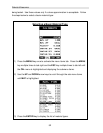
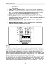
• Alarm Mode
• Gain Setting
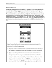
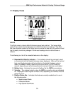
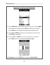
E. Digital Material Thickness Value – Extra large font size for viewing ease.
F. Scan Bar – Another view of material thickness in a deflection style horizontal
bar. This is another visual tool that would enable the user the ability to see
thickness changes during high speed scans from flaws and pits.
G. Units – The current measurement units being used (English, Metric).
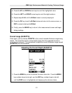
H. Coating Thickness Value – Displays the actual thickness of any coating
adhered to a metallic material surface (PECT Mode), or a coating adhered to a
non-metallic surface (CT Mode).
I. Minimum Material Thickness – Part of the Alarm feature. Displays the
minimum thickness value found during a scan.
J. Maximum Material Thickness – Part of the Alarm feature. Displays the
maximum thickness value found during a scan.
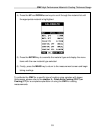
B-Scan View
B-Scan
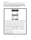
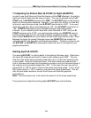
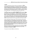
The B-Scan displays a time based cross section view of test material. This view is
commonly used to display the contour of the blind, or underside, surface of a pipe or
tank application. It is very similar to a fish finder. If a flaw or pit is located during a
scan, the B-Scan will draw the pit on the screen. The solid black rectangle in the
diagram at location K represents the cross section, or side view of the material. The
B-Scan view draws at a rate of 7 seconds per screen from right to left. Also notice at
location K, the pits and corroded bottom surface of the material.
It’s important to note that the measurement range on the display be set wide enough,
so that the maximum thickness of the material can be viewed on the display. Using
the diagram above, if the material thickness was actually 1.75”, the underside of the
material would not be viewable according to the current range at 0.00” – 1.00”. All