


Quick Installation Guide
00825-0100-4801, Rev KB
December 2010
Rosemount 3051S
12
STEP 4 CONTINUED...
NOTE
Wire colors provided on page 11 are per Belden 3084A DeviceNet cable. Wire color may
vary depending on cable selected.
Belden 3084A DeviceNet cable includes a ground shield. This shield must be connected to
earth ground at either the sensor module or the Remote Display, but not both.
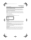
Quick Connect Wiring
As standard, the 3051S Quick Connect arrives properly assembled to the sensor module
and is ready for installation. Cordsets and Field Wireable Connectors (in shaded area) are
sold separately.
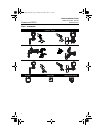
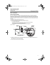
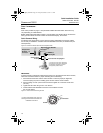
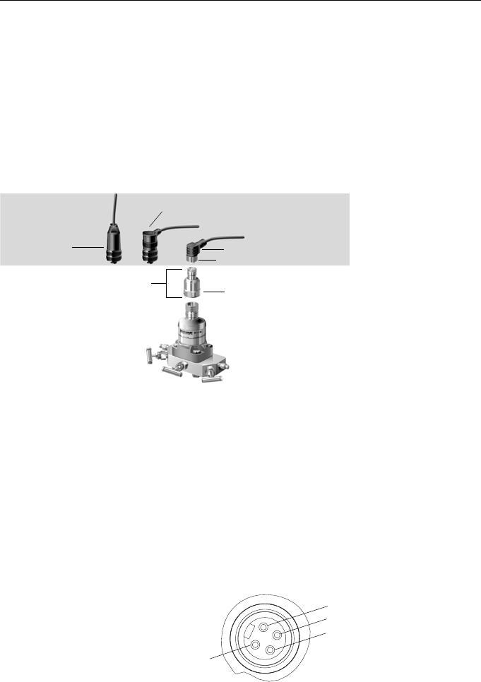
Figure 9. Rosemount 3051S Quick Connect Exploded View
IMPORTANT
If Quick Connect is ordered as a 300S spare housing or is removed from the sensor module,
follow the instructions below for proper assembly prior to field wiring.
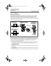
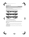
1. Place the Quick Connect onto the sensor module. To ensure proper pin alignment,
remove coupling nut prior to installing quick connect onto the sensor module.
2. Place coupling nut over quick connect and wrench tighten to a maximum of 300 in-lb.
(34 N-m).
3. Tighten the set screw using a
3
/32-in. hex wrench.
4. Install Cordset/ Field Wireable Connectors onto the Quick Connect.
Do not over tighten.
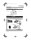
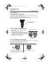
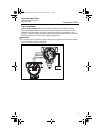
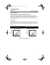
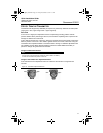
Figure 10. Quick Connect Housing Pin-Out
For other wiring details, refer to pin-out
drawing and the cordset manufacturer’s
installation instructions.
Straight Field
Wireable
Connector
(1)(3)
Right Angle Field Wireable
Connector
(2)(3)
Coupling Nut
Cordset
(4)
Quick Connect
Housing
Quick Connect Coupling Nut
(1) Order part number 03151-9063-0001.
(2) Order part number 03151-9063-0002.
(3) Field wiring supplied by customer.
(4) Supplied by cordset vendor.
“+”
“–”
Ground
No Connection
4801_QIG_RevKB.fm Page 12 Friday, December 3, 2010 1:17 AM