


Quick Installation Guide
00825-0100-4801, Rev KB
December 2010
Rosemount 3051S
7
STEP 1 CONTINUED...
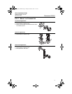
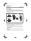
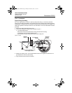
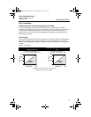
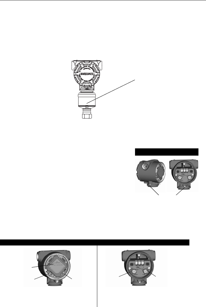
Inline Gage Transmitter Orientation
The low side pressure port (atmospheric reference) on the inline gage transmitter is located
under the sensor module neck label. (See Figure 3.)
Keep the vent path free of any obstruction, including but not limited to paint, dust, and lubrication
by mounting the transmitter so that any contaminants can drain away.
Figure 3. Inline Gage Transmitter
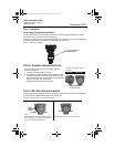
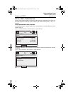
STEP 2: CONSIDER HOUSING ROTATION
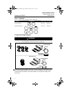
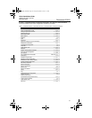
STEP 3: SET SWITCHES AND JUMPERS
If alarm and security adjustment option is not installed, the transmitter will operate normally with
the default alarm condition alarm high and the security off.
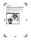
To improve field access to wiring or to better view the
optional LCD display:
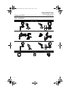
Figure 4. Transmitter Housing
Set Screw
1. Loosen the housing rotation set screw.
2. First rotate the housing clockwise to the desired location.
If the desired location cannot be achieved due to thread
limit, rotate the housing counter clockwise to the desired
location (up to 360° from thread limit).
3. Retighten the housing rotation set screw.
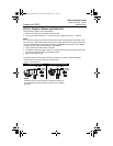
PlantWeb Junction Box
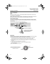
Figure 5. Transmitter Switch and Jumper Configuration
PlantWeb Junction Box
Slide the security and alarm switches into the
preferred position by using a small screwdriver.
(An LCD display or an adjustment module must
be in place to activate the switches.)
Pull the jumpers out and rotate 90° into
desired position to set the security and alarm.
Low side pressure port
(under neck label)
Housing Rotation Set
Screw (3/32-inch)
Alarm
Security
Meter/
Adjustment
Module
Security
Alarm
4801_QIG_RevKB.fm Page 7 Friday, December 3, 2010 1:17 AM