Quick Installation Guide
00825-0100-4801, Rev KB
December 2010
Rosemount 3051S
15
A check (ߛ) indicates the basic configuration parameters. At a minimum, these parameters
should be verified as part of the configuration and startup procedure.
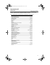
Table 1. Traditional Interface - Device Revision 6 or 7 and DD Revision 7 Fast Key Sequence
Function Fast Key Sequence
Alarm Level Configuration 1, 4, 2, 7, 7
Alarm and Saturation Levels 1, 4, 2, 7
Analog Output Alarm Direction 1, 4, 2, 7, 6
Analog Output Trim 1, 2, 3, 2
Burst Mode On/Off 1, 4, 3, 3, 3
Burst Options 1, 4, 3, 3, 4
ߛ Damping 1, 3, 6
Date 1, 3, 4, 1
Descriptor 1, 3, 4, 2
Digital To Analog Trim (4-20 mA Output) 1, 2, 3, 2, 1
Field Device Information 1, 4, 4, 1
LCD Display Configuration 1, 3, 7
Loop Test 1, 2, 2
Lower Sensor Trim 1, 2, 3, 3, 2
Message 1, 3, 4, 3
Number of Requested Preambles 1, 4, 3, 3, 2
Pressure Alert Configuration 1, 4, 3, 5, 3
Poll Address 1, 4, 3, 3, 1
Poll a Multidropped Transmitter Left Arrow, 3, 1, 1
Remapping 1, 4, 3, 6
Rerange- Keypad Input 1, 2, 3, 1, 1
Saturation Level Configuration 1, 4, 2, 7, 8
Scaled D/A Trim (4–20 mA Output) 1, 2, 3, 2, 2
Scaled Variable Configuration 1, 4, 3, 4, 7
Self Test (Transmitter) 1, 2, 1, 1
Sensor Information 1, 4, 4, 2
Sensor Temperature 1, 1, 4
Sensor Trim 1, 2, 3, 3
Sensor Trim Points 1, 2, 3, 3, 5
Status 1, 2, 1, 2
ߛ
Tag 1, 3, 1
Temperature Alert Configuration 1, 4, 3, 5, 4
ߛ
Transfer Function
(Setting Output Type)
1, 3, 5
Transmitter Security (Write Protect) 1, 3, 4, 5
ߛ
Units (Process Variable) 1, 3, 2
Upper Sensor Trim 1, 2, 3, 3, 3
Zero Trim 1, 2, 3, 3, 1
4801_QIG_RevKB.fm Page 15 Friday, December 3, 2010 1:17 AM


