


Quick Installation Guide
00825-0100-4801, Rev KB
December 2010
Rosemount 3051S
5
STEP 1 CONTINUED...
Bolting Considerations
If the transmitter installation requires assembly of the process flanges, manifolds, or flange
adapters, follow these assembly guidelines to ensure a tight seal for optimal performance
characteristics of the transmitters. Use only bolts supplied with the transmitter or sold by
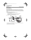
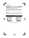
Emerson as spare parts. Figure 1 illustrates common transmitter assemblies with the bolt length
required for proper transmitter assembly.
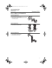
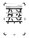
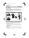
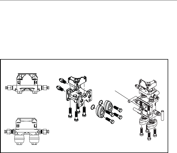
Figure 1. Common Transmitter Assemblies
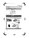
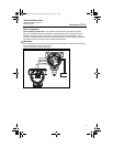
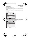
Bolts are typically carbon steel or stainless steel. Confirm the material by viewing the markings
on the head of the bolt and referencing Figure 2. If bolt material is not shown in Figure 2,
contact the local Emerson Process Management representative for more information.
Use the following bolt installation procedure:
1. Carbon steel bolts do not require lubrication and the stainless steel bolts are coated with a
lubricant to ease installation. However, no additional lubricant should be applied when
installing either type of bolt.
2. Finger-tighten the bolts.
3. Torque the bolts to the initial torque value using a crossing pattern. See Figure 2 for initial
torque value.
4. Torque the bolts to the final torque value using the same crossing pattern. See Figure 2 for
final torque value.
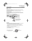
5. Verify that the flange bolts are protruding through the isolator plate before applying pressure.
4 x 1.75-in. (44 mm)
4 x 2.88-in. (73 mm)
A. Transmitter with
Coplanar Flange
B. Transmitter with Coplanar
Flange and Optional
Flange Adapters
C. Transmitter with Traditional
Flange and Optional Flange
Adapters
D. Transmitter with
Coplanar Flange and
Optional Manifold and
Flange Adapters
4 x 1.75-in. (44 mm)
4 x 1.50-in. (38 mm)
4 x 1.75-in. (44 mm)
4 x 2.25-in. (57 mm)
4801_QIG_RevKB.fm Page 5 Friday, December 3, 2010 1:17 AM