


Quick Installation Guide
00825-0100-4801, Rev KB
December 2010
Rosemount 3051S
8
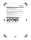
STEP 4: CONNECT WIRING AND POWER UP
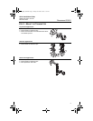
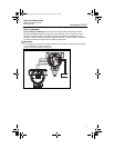
Use the following steps to wire the transmitter:
1. Remove the housing cover labeled “Field Terminals.”
2. Connect the positive lead to the “+” terminal, and the negative lead to the “–” terminal.
NOTE
Do not connect the power across the test terminals. Power could damage the test diode in the
test connection. Twisted pairs yield best results. For single compartment housing (Junction Box
housing), shielded signal wiring should be used in high EMI/RFI environments. Use 24 AWG to
14 AWG wire and do not exceed 5,000 feet (1500 meters).
3. Plug and seal the unused conduit connection.
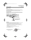
4. If applicable, install wiring with a drip loop. Arrange the drip loop so the bottom is lower than
the conduit connections and the transmitter housing.
5. Replace the housing cover.
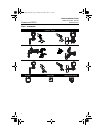
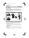
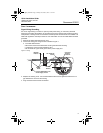
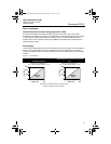
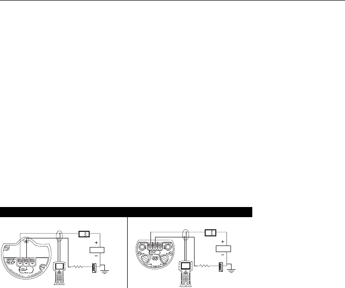
The figures below show the wiring connections necessary to power a 3051S and enable
communications with a hand-held Field Communicator.
Figure 6. Transmitter Wiring
PlantWeb Housing Wiring Junction Box Housing Wiring
NOTE
Installation of the transient protection terminal block does not
provide transient protection unless the 3051S case is properly
grounded.
RL 250
Power
Supply
Power
Supply
RL 250
4801_QIG_RevKB.fm Page 8 Friday, December 3, 2010 1:17 AM