


Quick Installation Guide
00825-0100-4801, Rev KB
December 2010
Rosemount 3051S
13
STEP 4 CONTINUED...
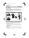
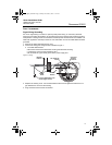
Conduit Electrical Connector Wiring (Option GE or GM)
For 3051S transmitters with conduit electrical connectors GE or GM, refer to the cordset
manufacturer’s installation instructions for wiring details. For FM Intrinsically Safe, non-incendive
or FM FISCO Intrinsically Safe hazardous locations, install in accordance with Rosemount
drawing 03151-1009 to maintain outdoor rating (NEMA 4X and IP66.) See Appendix B of the
3051S reference manual.
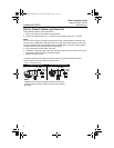
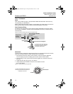
Power Supply
The dc power supply should provide power with less than two percent ripple. The total resistance
load is the sum of the resistance of the signal leads and the load resistance of the controller,
indicator, and related pieces. Note that the resistance of intrinsic safety barriers, if used, must be
included.
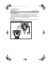
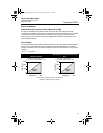
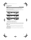
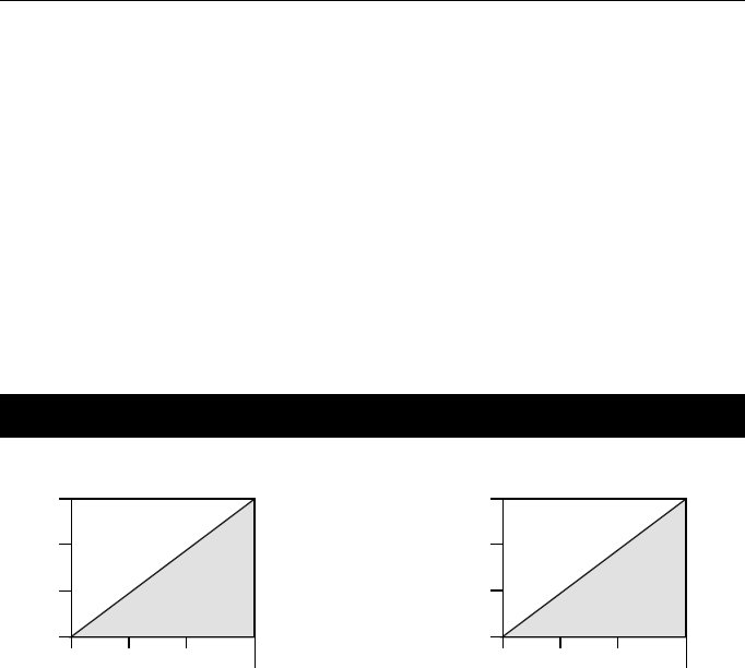
Figure 11. Load Limitation
Standard Transmitter
HART Diagnostics Transmitter (option code
DA1)
Maximum Loop Resistance =
43.5 * (Power Supply Voltage – 10.5)
Maximum Loop Resistance =
43.5 * (Power Supply Voltage – 12.0)
The Field Communicator requires a minimum loop
resistance of 250 for communication.
Voltage (Vdc)
Load (Ohms)
Operating
Region
1387
1000
500
0
10.5 20 30
42.4
Voltage (Vdc)
Load (Ohms)
Operating
Region
1322
1000
500
0
12.0 20 30
42.4
4801_QIG_RevKB.fm Page 13 Friday, December 3, 2010 1:17 AM