


Quick Installation Guide
00825-0100-4801, Rev KB
December 2010
Rosemount 3051S
19
NOTES
1. Transmitter output is not safety-rated during the following: configuration changes, multidrop,
loop test. Alternative means should be used to ensure process safety during transmitter
configuration and maintenance activities.
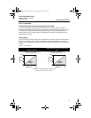
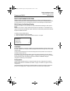
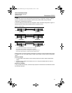
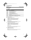
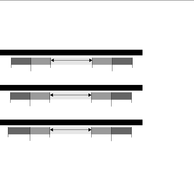
2. DCS or safety logic solver should be configured to match transmitter configuration. Figure 15
identifies the three alarm levels available and their operation values.
Figure 15. Alarm Levels
Setting the alarm values and direction is dependent on whether or not the hardware switch option
is installed. You can use a HART master or Field Communicator to set the Alarm and Saturation
values.
Switches installed
1. If using a Field Communicator, use the fast key sequence to set the Alarm and Saturation
values.
2. Manually set the direction for the Alarm to HI or LO using the ALARM switch as shown in
Figure 5 on page 7.
Switches not installed
If using a Field Communicator, use the fast key sequence to set the Alarm and Saturation values
and the Alarm Direction.
Rosemount Alarm Level
Namur Alarm Level
Custom Alarm Level
(3)(4)
(1) Transmitter Failure, hardware or software alarm in LO position.
(2) Transmitter Failure, hardware or software alarm in HI position.
(3) High alarm must be at least 0.1 mA higher than the high saturation value.
(4) Low alarm must be at least 0.1 mA lower than the low saturation value.
Normal Operation
4 mA
20 mA
20.8 mA
high saturation
21.75
(2)
3.9 mA
low saturation
3.75 mA
(1)
Normal Operation
4 mA
20 mA
20.5 mA
high saturation
22.5
(2)
3.8 mA
low saturation
3.6 mA
(1)
Normal Operation
4 mA
20 mA
20.1 - 20.5 mA
high saturation
20.2 - 23.0
(2)
3.7 - 3.9 mA
low saturation
3.6 - 3.8 mA
(1)
4801_QIG_RevKB.fm Page 19 Friday, December 3, 2010 1:17 AM