5
2. WIRING
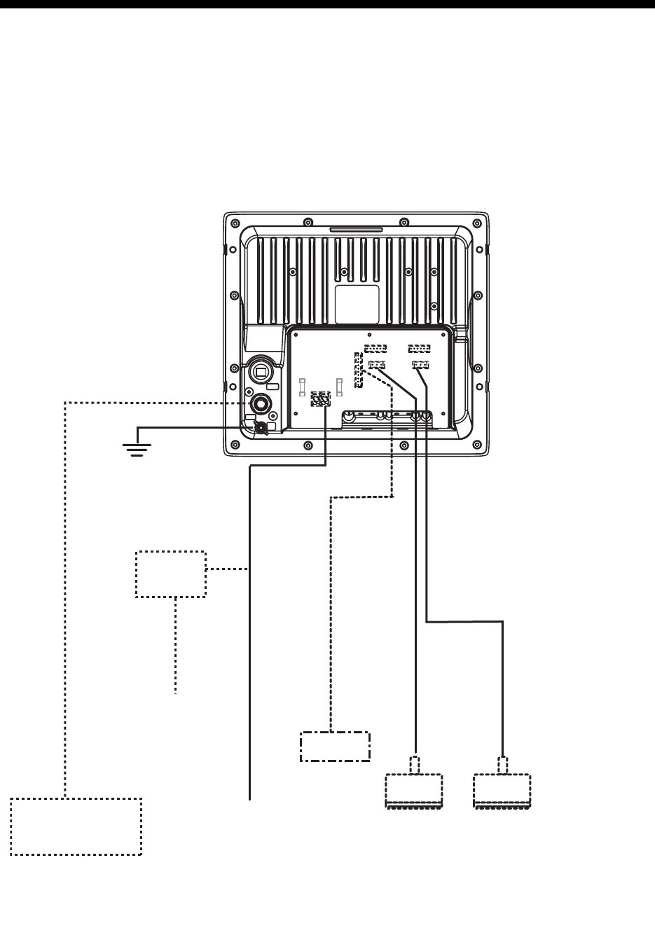
2.1 Interconnection
Refer to the interconnection diagram at the back of this manual for detailed information.
Wiring diagram for FCV-295
Low
Transducer
Speed/
Water temperature
sensor
Navigator
12-24 VDC
DPYCY-1.5
DPYCY-1.5
Rectifier
PR-62
100/110/115/
220/230 VAC
1
φ
, 50/60 Hz
*
Transducer
*
*: This unit cannot accept transducers of
53 to 65 kHz, 111 to 139 kHz and 171
to 183 kHz.
IV-2.0sq
Display unit rear panel
(connector cover removed)
High
MJ-A6SPF0003-050C
(Connect to a dedicated
breaker in the power
distributor.)
Grounding wire:
As short as possible


