


2-2
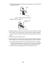
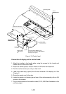
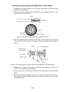
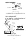
6. Determine the length of each core considering its location on STB-1 in the
scanner unit (see the interconnection diagram on page S-1). Remove approx.
6 mm of the vinyl insulation from the end of each core and fix the crimp-on lug
FV1.25-M3 (Red) to each core.
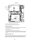
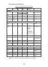
STB-2
STB-1
STB-3
Photo No.2872
Figure 2-3 Scanner unit, cover opened
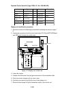
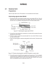
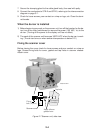
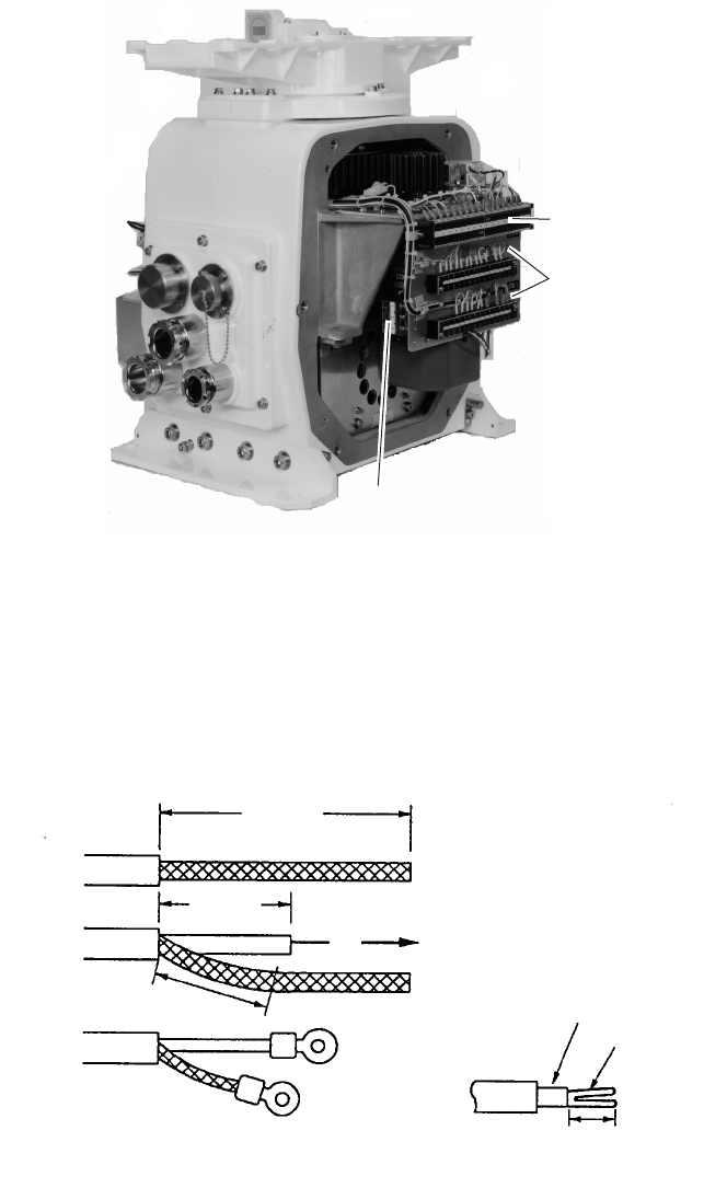
7. Remove the outer sheath of the coaxial cable (2C-2V) by 75 mm. Pull back
the braided shield to expose the inner core. Remove approx. 25 mm of insu-
lator from the end of inner core and fold back conductor as illustrated below.
Shorten the shield leaving approx. 45 mm. Fit crimp-on lugs to the conductor
(FVD1.25-3, Red) and braided shield (FV1.25-M3, Red).
Coaxial cable
2C-2V
50 mm
45 mm
Fold back the conductor
as illustrated below.
75 mm
Inner core
Conductor
6 mm
Crimp-on lug
FVD1.25-3
(Red, ∅3)
Crimp-on lug
FV1.25-M3
(Red, ∅3)
Figure 2-4 Fabrication of coaxial cable
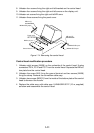
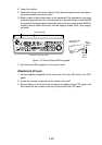
8. Slip the cable gland over the cable and tighten the cable gland nut. Seal the
cable gland nut with putty to preserve watertight integrity.
9. Connect wiring to terminal STB-1 referring to the interconnection diagram.