


4-15
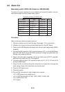
4.5 Alarm Kit
Necessary parts: OP03-156 (Code no. 008-500-650)
The alarm kit mainly consists of a circuit board and connection cables, and pro-
vides alarm output to ship’s bridge alarm system.
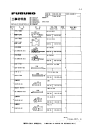
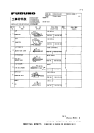
Contents of Alarm Kit OP03-156
emaNepyT.oNedoCytQ
draoBMRALA2629P30086-005-8001
.yssArotcennoCHN)P9-9(0991-30007-005-8001
.yssArotcennoCHN)P3(1991-30017-005-8004
dnaBelbaCN3-PH100-075-0001
eiTelbaC001-VC223-075-0003
BwercSdaeh-naPW0072C8X3M404-188-0004
BwercSdaeh-naPW0072C21X4M744-188-0001
Procedure
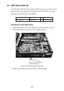
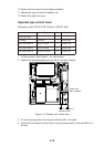
Refer to the figure below for parts locations.
1. Raise the monitor and fix it with the stay. (See page 1-5 for instructions.)
2. Unfasten four screws to dismount the shield cover for the INT Board.
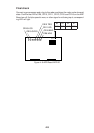
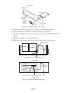
3. Fasten the ALARM Board to the display unit with four pan-head screws (M3X8,
supplied).
4. Connect the NH connector (9-9P, supplied) between J471 on the ALARM Board
and J451 (EXT-BUZ) on the INT Board, passing it through the cable band and
binding it with existing cable tie.
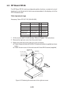
5. Fasten the cable band (supplied) with a pan-head screw (M4X12, supplied)
and attach two cable ties (CV-100, supplied).
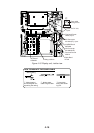
6. Connect an NH connector (3P, supplied) to each of J472, J473, J474 and J475
on the ALARM Board.
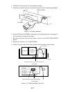
7. Route the NH connectors along the cables ties and pass them through the
cable clamp. Fasten the shield cover removed at step 1.
8. Close the INT board cover.
9. Close the monitor.
10.Connect NH connectors to ship’s bridge alarm system:
J472: ARPA guard zone; target alarm
J473: SYSTEM FAILURE (HP, BP, TRIG, VIDEO, GYRO, AZI)
J474: ARPA CPA/TCPA
J475: Spare