


4-14
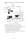
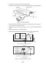
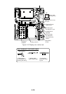
10.Fasten the front panel of the display pedestal.
11.Fasten the ground wire to the location shown in Figure 4-14.
12.Close the monitor.
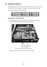
4.4 Performance Monitor PM-30
Necessary parts: PM-30 and OP03-150 (Code no. 008-485-490)
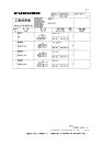
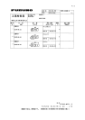
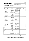
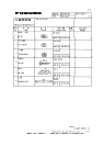
emaNepyTytQ.oNedoC
draoBMP5229P301026-784-800
wercSdaeHnaPW0072C8x3M3404-188-000
.yssArotcennoCAA-003L-P3HV2410-141-000
1. Lift the monitor. See Chapter 1 for instructions.
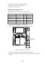
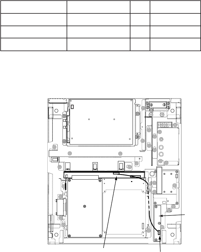
2. Fasten the PM Board 03P9225 to the location shown below with three screws
(M3 x 8).
J401
J411
PM Board
03P9225
Figure 4-15 Display unit, inside view
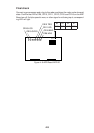
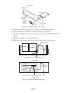
3. Connect the connector P401 coming from J411 to J401 on the PM Board.
4. Connect two connector assemblies (VH3P-L300-AA) to J402 and J403.
5. Solder the other end of there connector assemblies with external cables, one
from ship’s mains and one from the PM-30.
6. Close the monitor.