


2-8
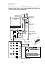
Connections
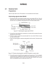
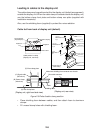
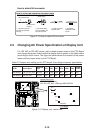
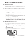
Open the display unit and fix it with the stay. (For procedure see page 1-6.)
Remove the shield cover from the INT Board. Connect signal, power, gyro and
log cables as shown on the next page. Optional equipment are connected to the
INT Board. Be sure to ground the display unit.
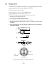
PTU Board
03P9245
INT Board
03P9252
GYRO CONVERTER
Board 64P1106
MOTHER Board
03P9251
J5
J4
Ground with this screw
(Console type only)
TB1
From power
supply unit
Scanner
Log
POWER Switch
(Normally ON)
J448
DJ1
J446
J467
J469
J448
J445
J449
J465
J455
J466
J454
J450
J462
J456
J453
J451
J458
J457
J452
J442
J443
J444
J463
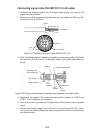
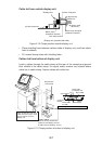
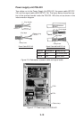
Plug in coax.
cable here.
Connect referring to
interconnection diagram.
Loosen screws on ter-
minal and slide terminal
forward.
INT Board
Connector Location
Fasten with M3x8 screw
(2 pcs., supplied).
Ground terminal
for pedestal mount
display unit
Ground terminal
for console mount
display unit
Gyro
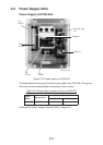
Figure 2-12 Display unit, inside view
1
7
3
4
5
2
8
6
M4X8 (2 pcs.)
1
2
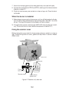
Ground the equipment to
prevent electrical shock
and mutual interference.
CAUTION
Bind cables so as not to pinch them
between the monitor and mounting base.
Pay special care tothe high voltage
line.