


2-4
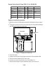
7. Secure the clamping gland to the cable gland body; then seal with putty.
8. Connect the conductors to STB-2 and STB-3, referring to the interconnection
diagram on page S-1.
9. Check for loose screws, poor contact on crimp-on lugs, etc. Close the termi-
nal boards.
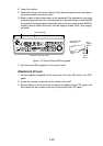
When the de-icer is installed
1) Before beginning any work on the scanner unit, turn off the breaker for the de-
icer line at the main switchboard to remove the power (100 VAC, 1ø) to the
de-icer. (Turning off the power to the display unit has no effect.)
2) The neck of the scanner unit becomes VERY HOT when the de-icer is work-
ing. (The de-icer turns on when ambient temperature is below 0°C.)
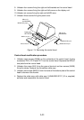
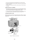
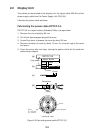
Fixing the scanner cover
Before closing the cover check for loose screws and poor contact on crimp-on
lugs. Grease fixing bolts for cover, gasket and tap holes in scanner chassis.
Attach cover.
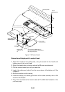
CHASSIS
Tap hole
Fixing
bolt (12 pcs.)
Apply silicone
grease here.
SCANNER
Scanner cover
Photo No.2871
Figure 2-7 Scanner unit, side view