


5
Plate
Bolt
4-M4 X 16
Gasket
Flat
washer
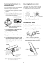
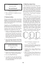
Figure 13 Passing the signal cable through
the cable gland assembly
5. Fasten the crimp-on lug on the shield to
one of the fixing bolts of the cable gland
assembly.
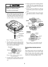
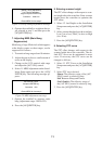
6. Position the signal cable so that no more
than 4 cm of the sheath is exposed as
shown in the figure below. Tighten fixing
bolts.
Sheath
CABLE GLAND
Plate
Gasket
Flat
washer
Bolt
Within 4 cm
Tubing
Shield
Figure 14 How to fix signal
cable in cable gland
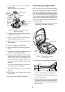
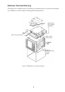
7. Unfasten four screws shown in the figure
below.
Four screws
Figure 15 Scanner unit chassis,
cover opened
8. Pass the signal cable through the cable
protector.
Cable
protector
Figure 16 Scanner unit chassis,
cover opened
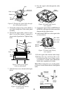
9. Connect the signal cable to the RTB Board
(03P9249), referring to the interconnection
diagram and the figure below.
10.Attach three EMI cores to the signal cable
as shown below.
Route cable along here.
Lead in
cable here.
J821 VH9P
J824 NH13P
J823 VH4P
EMI core
RFC-13
Clamp
Figure 17 Scanner unit chassis,
cover opened
11. Fix the signal cable with the cable clamp.
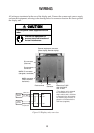
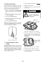
12.Release the stay and close the cover.
Loosely fasten the cover fixing screws;
you will have to make some adjustments
inside after completion of wiring.
Note: When closing the cover, set the gaskets
to grooves in the bottom chassis, then tighten
bolts.
BOTTOM
CHASSIS
GASKET
GROOVE
SCANNER BOLT
Torque : 9.8 ± 0.1N m