


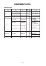
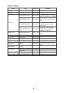
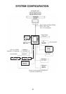

1
SCANNER UNIT
Mounting Considerations,
Precautions
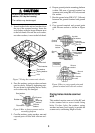
• The scanner unit is generally installed ei-
ther on top of the wheelhouse or on the ra-
dar mast on a suitable platform. Locate the
scanner unit where there is a good all-round
view. Any obstruction will cause shadow
and blind sectors. A mast for instance, with
a diameter considerably less than the width
of the radiator, will cause only a small blind
sector, but a horizontal spreader or
crosstrees in the same horizontal plane as
the scanner unit would be a much more
serious obstruction; you would need to
place the scanner unit well above or below
it.
• It is rarely possible to place the scanner unit
where a completely clear view in all direc-
tions is available. Thus, you should deter-
mine the angular width and relative bearing
of any shadow sectors for their influence
on the radar at the first opportunity after
fitting.
• If you have a radio direction finder on your
boat, locate its scanner clear of the scan-
ner unit to prevent interference to the di-
rection finder. A separation of more than
two meters is recommended.
• To lessen the chance of picking up electri-
cal interference, avoid where possible rout-
ing the signal cable near other onboard
electrical equipment. Also avoid running
the cable in parallel with power cables.
• A magnetic compass will be affected if
placed too close to the scanner unit. Ob-
serve the following compass safe distances
to prevent deviation of a magnetic com-
pass: Standard compass, 1.00 m, Steering
compass, 0.75 m.
• Do not paint the radiator aperture, to en-
sure proper emission of the radar waves.
• When this radar is to be installed on larger
vessels, consider the following points:
• The signal cable run between the scan-
ner and the display comes in lengths of
10 m (standard), 15 m, 20 m and 30 m.
Whatever length is used it must be un-
broken; namely, no splicing allowed.
• Deposits and fumes from a funnel or
other exhaust vent can adversely affect
the aerial performance and hot gases
may distort the radiator portion. The
scanner unit must not be mounted where
the temperature is more than 70°C.
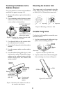
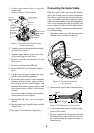
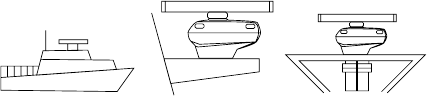
Mounting Methods
As shown in the figure below, the scanner unit
may be installed on the bridge, on a common
mast or on a dedicated mast.
(a) On bridge (b) Common mast (c) Dedicated mast
Figure 1 Scanner unit mounting methods
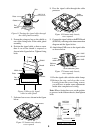
Fixing Holes in Mounting
Platform
Referring to the outline drawing on page D-
1, drill five holes in the mounting platform:
four holes of 15 mm diameter for fixing the
scanner unit and one hole of 25-30 mm diam-
eter for the signal cable.