


iii
TABLE OF CONTENTS
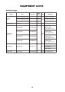
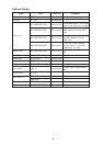
EQUIPMENT LISTS ..............................................................................................iv
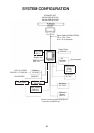
SYSTEM CONFIGURATION.................................................................................vi
SCANNER UNIT
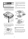
Mounting Considerations, Precautions ...............................................................................................1
Mounting Methods.............................................................................................................................1
Fixing Holes Mounting Platform........................................................................................................1
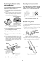
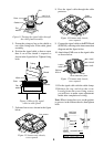
Fastening the Radiator to the Radiator bracket....................................................................................2
Mounting the Scanner Unit ................................................................................................................2
Outside fixing holes...........................................................................................................................2
Fixing holes inside scanner unit .........................................................................................................3
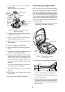
Connecting the Signal Cable..............................................................................................................4
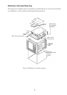
DISPLAY UNIT
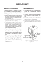
Mounting Considerations ...................................................................................................................6
Tabletop Mounting.............................................................................................................................6
Bulkhead, Overhead Mounting...........................................................................................................7
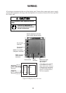
WIRING ..................................................................................................................8
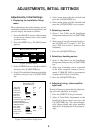
ADJUSTMENTS, INITIAL SETTINGS
Adjustments, Initial Settings
1.Displaying the Installation Setup menu...................................................................................9
2.Selecting a navaid ..................................................................................................................9
3.Selecting a heading sensor......................................................................................................9
4.Adjusting turning, video amplifier input level.........................................................................9
5.Aligning heading..................................................................................................................10
6.Adjusting sweep timing........................................................................................................10
7.Adjusting MBS (Main Bang Suppression)............................................................................11
8.Entering scanner height ........................................................................................................11
9.Selecting STC curve.............................................................................................................11
10.Setting a dead sector...........................................................................................................12
11.Checking magnetron heater voltage....................................................................................12
ARP-10 INSTALLATION
Necessary Parts................................................................................................................................13
Installation.......................................................................................................................................13
Adjustments.....................................................................................................................................14
INSTALLATION MATERIALS, ACCESSORIES, SPARE PARTS, PACKING LIST.........
A-1
OUTLINE DRAWINGS ....................................................................................... D-1
INTERCONNECTION DIAGRAM........................................................................
S-1