


8
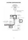
WIRING
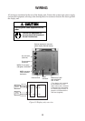
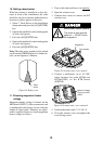
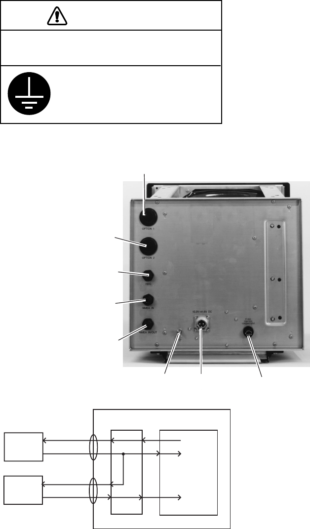
All wiring are terminated at the rear of the display unit. Connect the scanner unit, power supply
and external equipment, referring to the drawing below for connector location. Be sure to ground
the display unit.
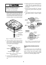
CAUTION
Use the power cable supplied with the
radar.
Ground the equipment to
prevent electrical shock and
mutual interference.
External equipment connector
(Slave display, Remote display)
DJ connector
(Scanner)
Gyrocompass
connector
NMEA I/O connector
(Navigator, see below)
NMEA connector
(Video Sounder,
see below)
Earth terminal
Power
connector
Power fuse F1351*
10A: 24/32 VDC
15A: 12 VDC
* The display unit is shipped
for connection to a 12 V
ship’s mains, and a 15A fuse
is inserted in the fuse holder.
For 24/32 V ship’s mains, re-
place the 15A fuse with the
10A fuse (supplied).
INT Board SPU Board
Navigator
(Plotter)
(RSD, TLL)
(L/L, WP...)
Depth, water
temperature
Video
Sounder
Figure 19 Display unit, rear view