


2-2
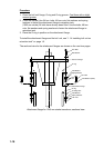
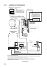
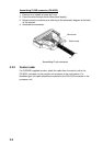
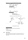
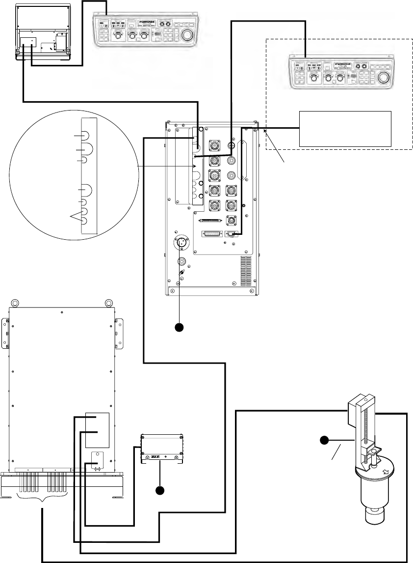
2.2 Location of Connectors
Monitor
(Local supply)
CONTROL UNIT FSV-2401
CONTROL UNIT FSV-2401
MONITOR UNIT
FSV-2400
PROCESSOR UNIT
FSV-2402/2402S
POWER SUPLY UNIT
FSV-242
TRANSCEIVER UNIT
FSV-241E
HULL UNIT
FSV-243E (1200 mm stroke)/
FSV-244E (1600 mm stroke)
10S2074 (10 m) or 10S2075 (30 m)
10S1258 (option)
Monitor cable
(Local supply)
DPYCY-4
10S2140 (15 m), 10S2141 (14.5 m)
10S2078 (8 m)
100/110/115/
220/230 VAC
1φ, 50/60 Hz
100/110/115/
220/230 VAC
1φ, 50/60 Hz
*2
*2: If connector may loosen by
vibration the monitor may also
be connected inside.
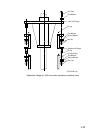
Processor unit clamp
Transceiver
unit
Monitor unit
Monitor unit
Control unit
Control unit
External
monitor
220 VAC
3φ, 50/60 Hz
10S2076 (5/10 m)
10S2076 (5/10 m)
DPYCY-1.5
*3
DPYCY-4
*3
*3
TPYCY-4
*3
*4
*4
*3: Japan Industrial Standard cable
*4: The same type of connector is fitted at each end, however the connector where the amount of sheath
removed is greater should be connected to the transceiver unit.
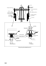
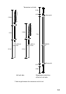
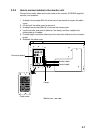
*5: When running the cables of 10S2078, 10S2140 and 10S2141, refer to next page.
*6: When using cable for extension kit, the length of the cable between the transceiver unit
and the hull unit is 10 m or 20 m.
*5 *6
*5 *6
Interconnection