


AP-3
DATA SHEET 2
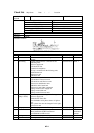
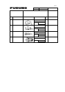
DISPALY UNIT (FSV-2400 )
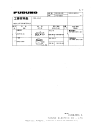
Check item Contents Check point CK Standard Result Judge
Check software version on
the each board
Self-check
display
DCON 1050714***
DUAL 1050703***
IFES 1050711***
KEY 1050685***
TRCPU 1050717***
Software
version
TRX 1050665***
to 1050684***
WC
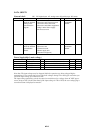
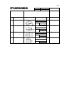
TRANSCEIVER UNIT(FSV-241)
Check item Contents Check point CK Meter reading Result Judge
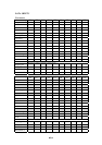
Test points on
the TRX boards.
1
st
layer
2
nd
layer
3
rd
layer
4
th
layer
5
th
layer
6
th
layer
7
th
layer
8
th
layer
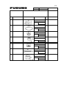
9
th
layer
10
th
layer
11
th
layer
12
th
layer
13
th
layer
14
th
layer
15
th
layer
16
th
layer
17
th
layer
18
th
layer
19
th
layer
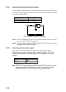
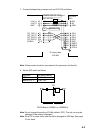
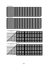
TX output Check transmission output
power voltage at following
conditions:
Range: 1000m
TX setting: 9-9-9
Tilt: 0
Stabilize.: OFF
TX weight: all 1
Measuring point
TP108-137
Measure peak-to-peak
voltage at 5ms from the
leading edge of the
transmission pulse.
There are 15 channels of
TX_P/N on each TRX
board. (Totally 600ch)
20
th
layer
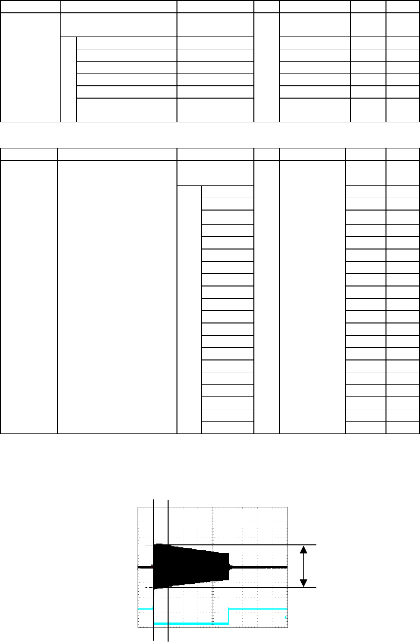
OS See fig 1
Fig 1 TX output power and B voltage
Normally, the output power voltage should read 1400Vp-p. However, it varies within ±15% because of
transducer impedance. B voltage is normally 120V at each transmission.
5ms
1400Vp-p