


AP-1
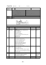
Check List
Ship Name Date / / Location
SCANNING
SONAR
TYPE FSV-24 RESULT
Monitor unit (FSV-2400) Options
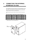
Control unit (FSV-2401) CS-120A
Processor unit (FSV-2402) VI-1100A
Transceiver unit (FSV-241E) CS-170
Power supply unit (FSV-242) FSV-2451(5m),FSV2452(15m)
Hull unit (FSV-243E/244E )
S/N
Reference
Frequency 24KHz
Transducer location
Note:
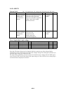
NO CHECK ITEMS CONTENT RESULT DATA
1 Unit installation All units are installed according to installation
manual.
Good/No Good
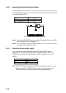
2 Grounding Copper plate should be connected for the
following units.
1.Power supply unit
2.Transceiver unit
3.Junction box(Option)
IV-8sq is connected for the following units.
1.Raise/lower box
2.Processor unit
3.Monitor unit
Good/No Good Sheet 1
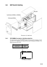
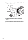
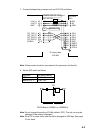
3 Connection Check the connection between each unit.
1.Transducer-Transceiver unit
2.Transceiver unit-Processor unit
3.Processor unit-Monitor unit
4.Monitor unit-Control unit
5.Processor unit- Other equipments
6.Ship’s mains-Power supply unit
7.Ship’s mains-Hull unit
8.Ship’s mains-Processor unit
Good/No Good Sheet 1
4 Power Supply
(Ship’s mains)
Check ship’s mains voltage for following units.
1.Power supply unit
2.Raise/lower motor line
Check whether led of phase detector is light or
not.
The 3 phase line must be changed if led is light.
3.Processor unit
Good/No Good Sheet 1
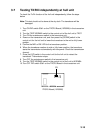
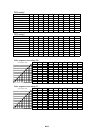
5 Output power Check output power and +B voltage. Good/No Good Fig1
6 Test Check the following tests.
Board test/Panel test/RX test/Channel
test1/Channel test2/Noise test
Good/No Good Sheet2
Installation
manual
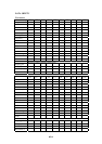
7 Setting Check the user program setting. Sheet3
8 Operation check Check pictures after turning on the power. Good/No Good