


2-5
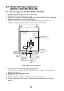
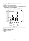
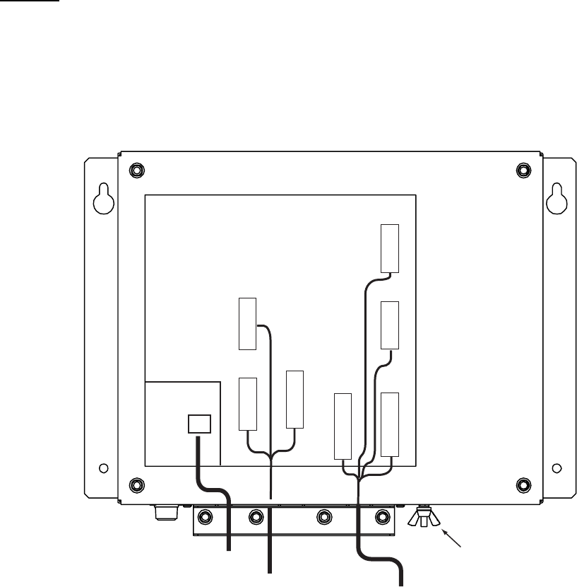
2.2.2 Power supply unit PSU-008 (MODEL1964C-BB)
Cabling
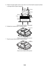
1. Unfasten four screws to remove the cable clamp.
2. Unfasten four screws to remove the cover.
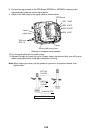
3. Attach the VL connector of the power supply cable VL3P-VV-S2X2C-AA050 (supplied as
installation materials) to J1 on the POWER Board.
4. Attach the VH and NH connectors of MJ-B24LPF0009-050 cable (supplied as
installation materials) to these locations: VH9, J3; VH4, J4, NH13, J5.
POWER Board 03P9419
J1
3P
VL3P-VV-S2X
2C-AA050
cable
(to 12-24 VDC)
MJ-B24
LPF0011-050
cable
(to processor unit)
V
H
9
N
H
13
V
H
4
J3
J4
J5
Ground
terminal
V
H
1
0
J12
N
H
1
4
J14
V
H
5
J13
V
H
2
J11
Antenna cable
RW-9771
(03S9771)
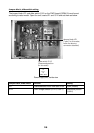
5. Connect the antenna cable to these locations: VH2, J11, VH10, J12; VH5, J13, NH14,
J14.
6. Lay three cables in respective slots referring to the figure above.
7. Reattach the cover (removed at step 2).
8. Reattach the cable clamp.
9. Connect a ground wire (local supply, IV-2sq) between the ground terminal and ship’s
ground.