


GPSMAP 700 Series Owner’s Manual 59
Radar
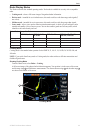
Showing AIS Vessels on the Radar Screen
AIS requires the use of an external AIS device and active transponder signals from other vessels.
You can congure how other vessels appear on the Radar screen. If any setting (except the AIS display range)
is congured for one radar mode, the setting is applied to every other radar mode. The details and projected
heading settings congured for one radar mode are applied to every other radar mode and to the Radar
Overlay.
1. From the Home screen, select .
2. Select , , , or .
3. Select > > .
4. Complete an action:
• Select to indicate the distance from your location within which AIS vessels appear,
and select a distance.
• Select > to show details about AIS-activated vessels.
• Select , enter the projected heading time for AIS-activated vessels, and select .
• Select to show the tracks of AIS vessels, and select the length of the track that appears using a
trail.
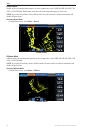
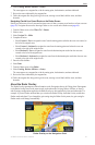
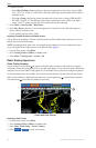
VRM and EBL
The variable range marker (VRM) and the electronic bearing line (EBL) measure the distance and bearing
from your boat to a target object. On the Radar screen, the VRM appears as a circle that is centered on the
present location of your boat, and the EBL appears as a line that begins at the present location of your boat and
intersects the VRM. The point of intersection is the target of the VRM and the EBL.
Showing the VRM and the EBL
The VRM and the EBL congured for one mode are applied to all other radar modes.
1. From the Home screen, select .
2. Select , , or .
3. Select > .
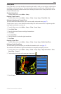
Adjusting the VRM and the EBL
You must show the VRM and the EBL before you can adjust them (page 59).
You can adjust the diameter of the VRM and the angle of the EBL, which moves the intersection point of the
VRM and the EBL. The VRM and the EBL congured for one mode are applied to all other radar modes.
1. From the Home screen, select .
2. Select , , or .
3. Select > > .
4. Touch a new location for the intersection point of the VRM and the EBL.
5. Select .
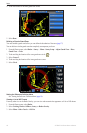
Measuring the Range and Bearing to a Target Object
You must show the VRM and the EBL before you can adjust them (page 59).
The VRM and the EBL congured for one mode are applied to all other radar modes.
1. From the Home screen, select .
2. Select , , or .
3. Select > > .
4. Touch the target location.
The range and the bearing to the target location appear in the upper-left corner of the screen.
5. Select .