


Service
309497L 23
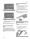
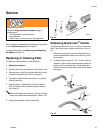
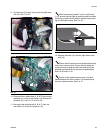
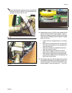
9. Pull the bezel (31) away and up from the right cover
half (18). See F
IG. 26.
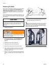
10. Disconnect the cables/wires (A, B, & C) that connect
the bezel (31) to the circuit board (112). Discard the
old bezel (31). See F
IG. 27 and FIG. 28.
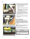
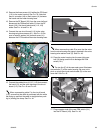
11. Reconnect the cables/wires (A, B, & C) from the
new bezel (31) to the circuit board (112).
When reconnecting cable C to the circuit board
(112), ensure that the cable is positioned with the white
tab facing up and that the cable is straight before push-
ing in (closing) the clasp. See F
IG. 28.
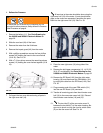
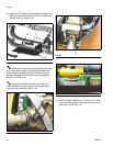
12. Replace the bezel (31) onto the right meter cover
half (18).
Ensure that all meter parts are positioned securely
and in the correct location. Ensure that all cables are
routed correctly throughout the meter and will not be
pinched or kinked when the halves are reassembled
See F
IG. 29 and FIG. 30.
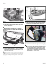
Ensure that the black antenna wire is not posi-
tioned between the ribbon cables. Pull antenna away
from the cable as shown. See F
IG. 31.
F
IG. 26
F
IG. 27
A
C
B
FIG. 28