


Service
309497L 27
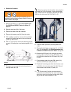
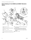
18. Assemble the covers (18 &19). Insert several of the
screws to hold the cover halves together. Test the
display and trigger by inserting a battery and power-
ing on the unit. If display does not appear or trigger
does not function:
• make sure that a charged battery (11) is being
used.
• check that the connections from the new bezel
(31) to the circuit board (112) are fastened cor-
rectly and securely.
• check that all parts are repositioned securely
and in the correct location.
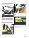
• check that the trigger connection to the RF
board (103) is fastened correctly and securely.
• check that the trigger switch is centered prop-
erly and that no gaps have formed between the
switch and circular indent.
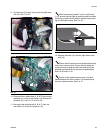
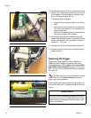
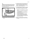
19. If the display appears, test the trigger to be sure that
both dispense settings work correctly. Replace the
remaining screws (12) and (42) that hold the cover
halves together. Torque all screws to 7 - 10 in. lbs.
Ensure that the black antenna wire is not positioned
between the ribbon cables. Pull antenna away from
the cable as shown. See F
IG. 40.
F
IG. 38
F
IG. 39
FIG. 40