


Service
309497L 25
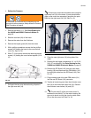
1. Relieve the Pressure.
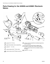
1. Remove the battery (11). See Parts Drawing for
the 246008 and 249881 Electronic Meters on
page 32.
2. Slide the rear boot (24) off the hose.
3. Remove the meter from the fluid hose.
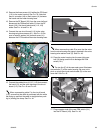
4. Remove the impact guard (40) from the meter.
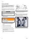
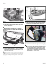
5. With a phillips screwdriver remove the four phillips
screws (42) holding the bezel to the cover halves
(18 & 19). See F
IG. 32.
6. With a T-10 torx driver remove the remaining eleven
screws (12) holding the cover halves together (18 &
19).
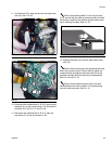
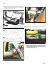
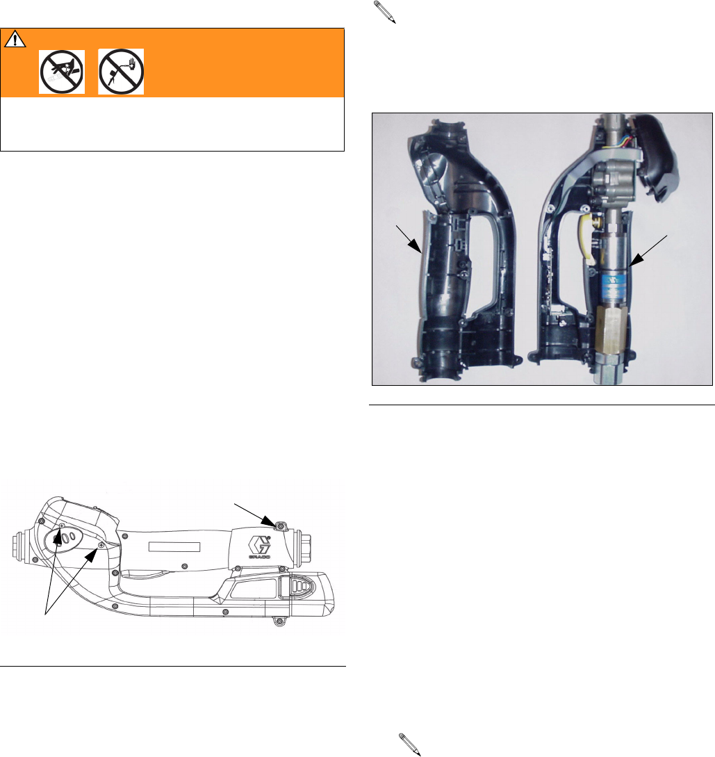
7. Pull apart the two cover halves leaving all parts in
the right cover half (18).
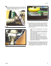
All services to the meter should be done using the
right cover half (18) of the meter. If parts should disen-
gage as the covers are separated, reposition the parts
back into the right cover half (18). See F
IG. 33.
8. Place the new right cover (18) along side of the
meter.
9. Remove the old trigger components (13, 14, 22, 23,
36, & 37) and discard.
See
Parts Drawing for the
246008 and 249881 Electronic Meters
on page 32.
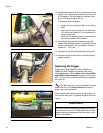
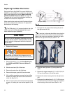
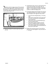
10. Remove the RF Board (103) from the right meter
housing (18) and disconnect the PSM switch (101)
by pulling the cable from the RF Board (103). See
F
IG. 35.
11. Plug connector end of the new PSM switch (101)
into the new RF Board (103) connector.
12. Transfer all remaining parts from the old meter cover
half (18) to the new meter cover half (18). Discard
the old meter cover halves (18) and (19).
13. The two ribs (E) of the new meter cover fit
between the two bolts (F) of the meter housing. Be
sure not to pinch or crimp the circular switch cable
(D) on the new cover half. See F
IG. 34.
WARNING
To reduce the risk of serious injury whenever you are
instructed to relieve pressure, always follow the Pressure
Relief Procedure on page 8.
FIG. 32
42 (both sides)
12
F
IG. 33
19
18