


Setup
3A1569B 19
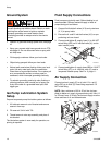
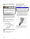
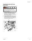
Recirculation / Pressure Relief
Lines
If Recirculating to Supply Drum: Connect high
pressure hose (R) to relief fittings (BA, BB) of both
PRESSURE RELIEF/SPRAY valves. Route hose back
to component A and B drums. Refer to manual 309852.
Alternate recirculation hoses (requires adapter
fittings):
249508 - ISO (A) (moisture guard) red hose, 1/4 in. (6
mm) ID; #5 JIC fittings (m x f); 35 ft (10.7 m) long.
249509 - Resin (B) blue hose; 1/4 in. (6 mm) ID, #6 JIC
fittings (m x f), 35 ft (10.7 m) long.
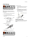
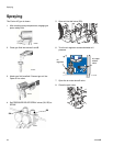
Install Fluid Temperature Sensor
(FTS)
Install FTS between main hose and whip hose. See
Heated Hose manual for instructions.
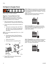
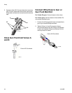
Connect Heated Hose
NOTE: See heated hose manual for detailed instruc-
tions for Graco heated hoses.
1. Turn main power OFF.
2. Assemble heated hose sections, FTS, and whip
hose. See Heated Hose manual for instructions.
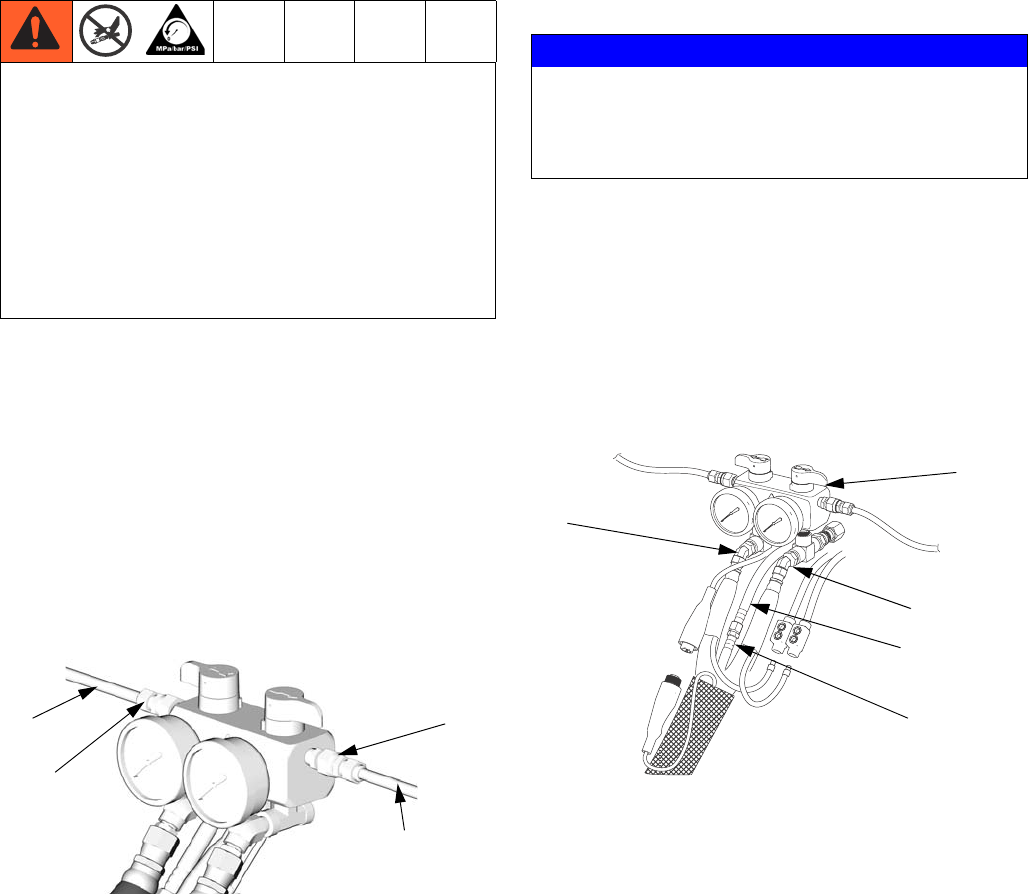
3. Connect A and B hoses to A and B outlets on
Reactor fluid manifold (FM). Hoses are color coded:
red for component A (ISO), blue for component B
(RES). Fittings are sized to prevent connection
errors.
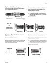
NOTE: Manifold hose fittings (VV, WW) allow use of 1/4
in. and 3/8 in. ID Reactor heated fluid hoses.
4. Connect heated hose air line (AH) to proportioner
air hose.
Do not install shutoffs downstream of the
PRESSURE RELIEF/SPRAY valve outlets (BA, BB).
The valves function as over pressure relief valves
when set to SPRAY. Lines must be open so valves
can automatically relieve pressure when machine is
operating.
If circulating fluid back to the supply drums, use high
pressure hose rated to withstand the maximum
working pressure of this equipment.
BB
BA
ti8441a
R
R
NOTICE
The fluid temperature sensor (FTS) and whip hose
must be used with heated hose; see page 19. Hose
length, including whip hose, must be 60 ft (18.3 m) min-
imum.
FM
VV
WW
ti17788a
AH
PH