


Spraying
3A1569B 25
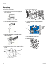
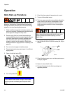
9. Slowly increase the air regulator setting until the
approximate stall (static) pressure is achieved on
fluid gauges (GA) and (GB).
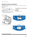
10. Check fluid pressure gauges (GA, GB) to ensure
proper pressure balance. If imbalanced, reduce
pressure of higher component by slightly turning
PRESSURE RELIEF/SPRAY valve for that
component toward PRESSURE
RELIEF/CIRCULATION, until gauges show
balanced pressures.
NOTE: Ensure relief tubes are in waste containers.
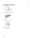
11. Open gun fluid inlet valves A and B.
12. Disengage gun piston safety lock.
13. Test spray onto cardboard. Adjust the air regulator
to get the minimum fluid pressure that results in a
good spray pattern.
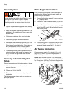
NOTE: Pumps have fluid to air ratio of 25 to 1. Feed
pumps add 2X feed pressure boost to outlet pressure
(on the up stroke only). For best results, use regulators
on feed pumps to limit inlet feed pressure to approxi-
mately 100 psi (0.7 MPA, 7 bar).
14. Check A and B fluid pressure gauges (GA, GB) to
ensure proper pressure balance between A and B.
15. Equipment is ready to spray.
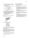
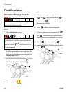
Spray Adjustments
Flow rate, atomization, and amount of overspray are
affected by four variables.
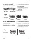
• Fluid pressure setting. Too little pressure results in
an uneven pattern, coarse droplet size, low flow,
and poor mixing. Too much pressure results in
excessive overspray, high flow rates, difficult control,
and excessive wear.
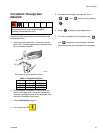
• Fluid temperature. Effects are similar to when fluid
pressure setting is too high or too low.
• Mix chamber size. Choice of mix chamber is based
on desired flow rate within machine capability and
fluid viscosity.
• Cleanoff air adjustment. Too little cleanoff air
results in droplets building up on the front of the
nozzle, and no pattern containment to control over-
spray. Too much cleanoff air results in air-assisted
atomization and excessive overspray.
ti8441a
GA
GB
SB
SA
ti2414a
ti2410a