


6
Installa
Installa
tion C
tion C
onfirma
onfirma
tion
tion
Refer to the Matrix Installation Guide for specific installation and cabling
instructions for your Matrix unit and for the transducer. Refer to the GPS
Installation Guide also included with your Matrix unit for specific installation and
cabling instructions for your GPS Receiver. Once you have installed the Matrix, the
transducer and the GPS Receiver, you should confirm that the GPS is installed
correctly. Press POWER to turn on your Matrix unit. Immediately press the MENU
button to display a screen list of Start-Up options. Use the 4-Way Cursor key to
select System Status from the Start-Up menu.
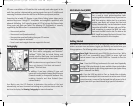
Press the VIEW key until the System Status/Accessory Test View is displayed. This
view displays the connection status for each accessory. If your GPS Receiver is
connected properly and it is communicating with your Matrix unit, it will be
shown as CONNECTED.
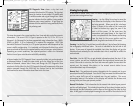
After the GPS Receiver is shown as CONNECTED, press the VIEW key again until the
GPS Diagnostic View is displayed. The GPS Diagnostic View will display acquired
satellites and their status, including signal strength. Your GPS Receiver will not
provide valid signals until it acquires at least two satellites. Acquisition can take
several minutes if this is the first use of your Receiver. This time lag also happens
if you have moved a significant distance since the GPS Receiver was last used.
In Start-Up mode, the GPS Diagnostic View can be viewed as one of the available
views if a GPS receiver is detected. It will not be available if the GPS receiver is not
detected. In Normal mode, the GPS Diagnostic View is normally hidden, but can be
viewed as an Advanced feature. To make this view visible, go to the Setup Tab, set
the User Mode to Advanced, choose Select Views, and change the GPS Diagnostic
View selection to Visible. After this, the GPS Diagnostic View will become part of
the view rotation accessed through the VIEW key.
7
S
S
yst
yst
em S
em S
ta
ta
tus - S
tus - S
tar
tar
t
t
-Up Menu
-Up Menu
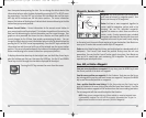
When System Status is selected on the Start-Up menu, the Matrix displays a
series of views to provide information about the unit. The following views are
displayed in turn when you press the VIEW button:
• Self Test
• Accessory Test
• GPS Diagnostic View
• Sonar Test (RTS Sonar Diagnostic).
Self Test displays results from internal diagnostic self test, including unit serial
number, software revision, total hours of operation and the input voltage from the
power source.
Accessory Test lists the accessories connected to the system. Note that the speed
accessory is only detected when the paddleswheel is moving.
GPS Diagnostic appears if the GPS Receiver is connected, and displays status
information from the GPS Receiver. See Navigation Views for more information.
Sonar Test (RTS Sonar Diagnostic) displays unprocessed sonar returns on the
display to confirm that sonar is working.
Exit System Status mode by powering the unit off.
PC C
PC C
onnec
onnec
t - S
t - S
tar
tar
t
t
-Up Menu
-Up Menu
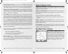
When you select PC Connect from the Start-Up Menu, the Matrix unit enters a
communication mode and waits for a connection with a PC. Complete
instructions are included with the PC Connect accessory (AS-PC). Exit PC Connect
mode by powering the unit off.
M5565_ManE_531192-1_A.qxd 5/4/2003 9:38 PM Page 10