


3 - 4
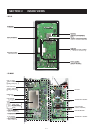
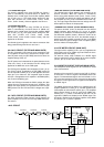
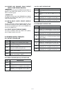
3-2-5 RF CIRCUIT (MAIN, PA UNITS AND DRIVER
BOARD)
The RF circuit amplifies operating (transmitting) frequency
to obtain 150 W of RF output.
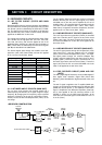
The signal from the 1st IF mixer is passed through one of the
low-pass filter or bandpass filters (Refer to page 4-1 band-
pass filters used), and then applied to the YGR amplifier
(IC1, pin 1) after being passed through the attenuator
(R5–R7). The amplified signal passes through the low-pass
filter (L1–L3, C1–C7) and attenuator (R1–R3), and then
applied to the PA unit via J1.
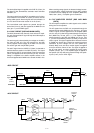
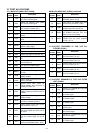
The signal applied from the MAIN unit is amplified at 2
amplifiers (PA unit; Q6101 and Q6801). A part of output sig-
nal from 2 amplifiers are applied to the amplifiers to improve
the frequency characteristic by feedback. The amplified sig-
nal is applied to the drive amplifier (DRIVER board; Q6851)
via the J6301 as “DRVI” signal. The signal from the DRIVER
board passes through the impedance converter (PA unit;
L6301), and then applied to push-pull amplifiers (PA unit;
Q6401, Q6402) to obtain a stable 150 W of RF output
power. A part of the RF output power returns to the ampli-
fiers to obtain a stable gain between 1.6 MHz and 27.5 MHz
bands by using feedback transformer (L6404). The output
power is applied to the filter unit via the J6401 as “FLIN” sig-
nal.
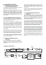
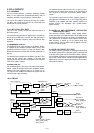
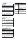
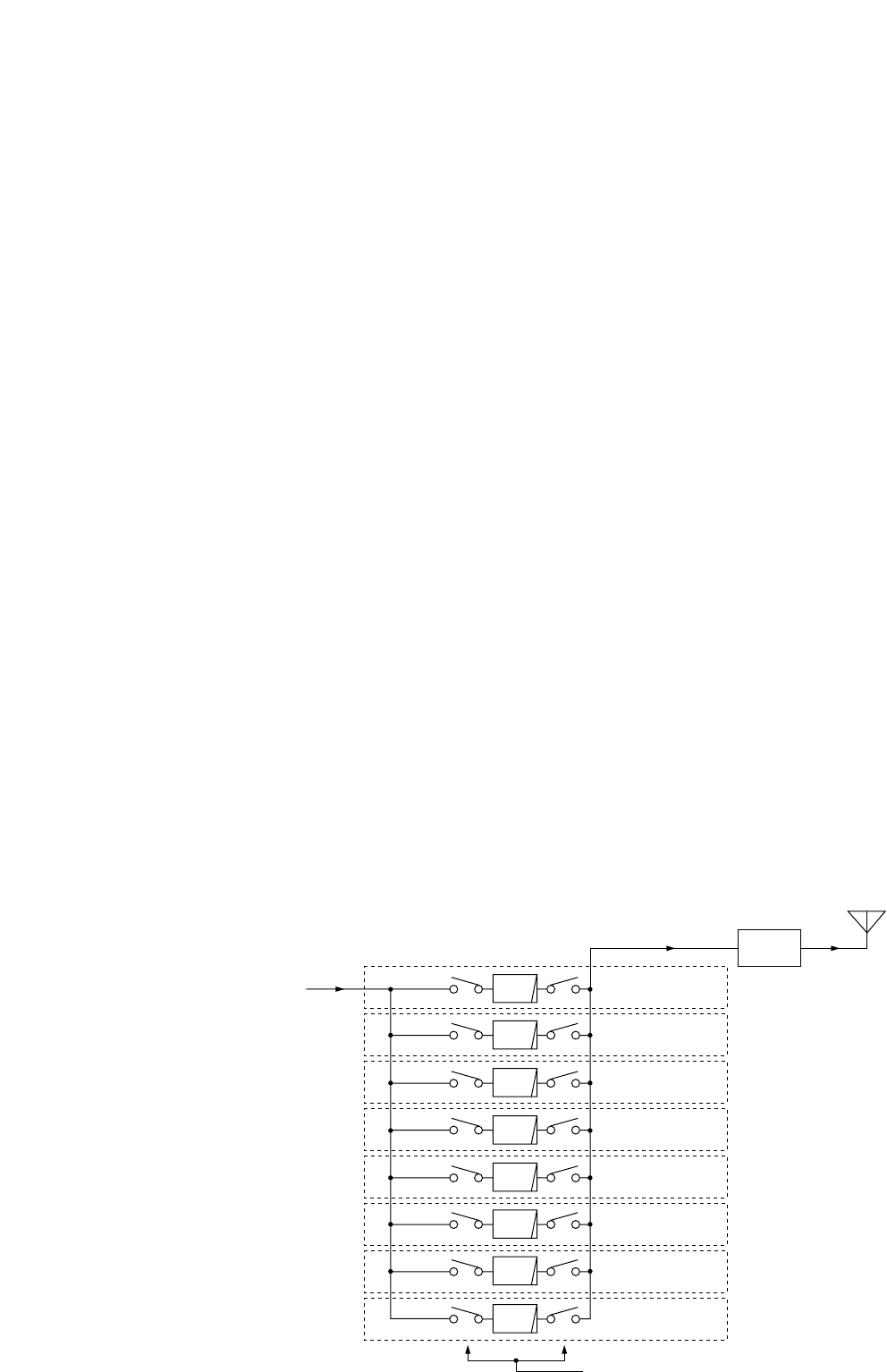
The amplified signal is applied to the one of the 8 low-pass
filters which are composed chebychev type.
• 1.6–1.9999 MHz signal
The signal is applied to the relay (FILTER unit; RL7031)
which is controlled by the band control IC (MAIN unit;
IC3602) as the “L1M” signal via the buffer amplifier (MAIN
unit; IC1301, pin 11). The signal passes through the low-
pass filter (FILTER unit; L7036–L7038, C7033–C7039,
C7041–C7045, C7049), and then applied to the RL7032.
• 2–2.9999 MHz signal
The signal is applied to the relay (FILTER unit; RL7061)
which is controlled by the band control IC (MAIN unit;
IC3602) as the “L2M” signal via the buffer amplifier (MAIN
unit; IC1301, pin 12). The signal passes through the low-
pass filter (FILTER unit; L7066–L7068, C7063–C7084,
C7086, C7087), and then applied to the RL7062.
• 3–4.9999 MHz signal
The signal is applied to the relay (FILTER unit; RL7091)
which is controlled by the band control IC (MAIN unit;
IC3602) as the “L4M” signal via the buffer amplifier (MAIN
unit; IC1301, pin 12). The signal passes through the low-
pass filter (FILTER unit; L7096–L7098, C7094–C7096,
C7098–C7101, C7105–C7107), and then applied to the
RL7092.
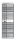
• 5–6.9999 MHz signal
The signal is applied to the relay (FILTER unit; RL7121)
which is controlled by the band control IC (MAIN unit;
IC3602) as the “L6M” signal via the buffer amplifier (MAIN
unit; IC1301, pin 14). The signal passes through the low-
pass filter (FILTER unit; L7126–L7128, C7124–C7132,
C7136, C7137), and then applied to the RL7122.
• 7–9.9999 MHz signal
The signal is applied to the relay (FILTER unit; RL7151)
which is controlled by the band control IC (MAIN unit;
IC3602) as the “L8M” signal via the buffer amplifier (MAIN
unit; IC1301, pin 15). The signal passes through the low-
pass filter (FILTER unit; L7066–L7068, C7063–C7084,
C7086, C7087), and then applied to the RL7152.
• 10–13.9999 MHz signal
The signal is applied to the relay (FILTER unit; RL7181)
which is controlled by the band control IC (MAIN unit;
IC3602) as the “L12M” signal via the buffer amplifier (MAIN
unit; IC1301, pin 16). The signal passes through the low-
pass filter (FILTER unit; L7182–L7184, C7183–C7188,
C7193), and then applied to the RL7182.
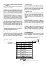
Antenna
power
detector
LPF
LPF
Filter: L0
1.6—1.9999 MHz
Filter: L1
2—2.9999 MHz
Filter: L2
3—4.9999 MHz
Filter: L3
5—6.9999 MHz
Filter: L4
7—9.9999 MHz
Filter: L5
10—13.9999 MHz
Filter: L6
14—19.9999 MHz
Filter: L7
low-pass filter control signals
from the MAIN unit
20—29.9999 MHz
LPF
LPF
LPF
LPF
LPF
LPF
(L1M, L2M, L4M, L6M, L8M, L16M, L22M)
Transmitter signals
from the PA unit.
• RF FILTER CIRCUIT