


3 - 8
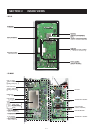
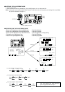
3-5-3 GROUP AND CHANNEL DIALS CIRCUIT
(DISPLAY AND SENSOR BOARDS)
• GROUP DIAL
The signals from the group dial (SENSOR board; S8801) is
applied to the FRONT CPU (IC8201, pins 76, 77) via the
“GPA” and “GPB” signals.
• CHANNEL DIAL
The signals from the channel dial (SENSOR board; S8802)
is applied to the FRONT CPU (IC8021, pins 74, 75) via the
“CHA” and “CHB” signals.
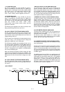
3-5-4 KEY’S BACK LIGHTS CIRCUIT (DISPLAY
BOARD)
The key”s back lights compose DS8340–DS8350, and are
controlled by the dimmer circuit (Q8340–Q8345). The dim-
mer circuit is controlled by the CPU via the “DIMMER” sig-
nal from the FRONT CPU.
3-5-5 RESET CIRCUIT (DISPLAY BOARD)
The reset IC (IC8202) resets the FRONT CPU (IC8201)
when IC-M802 is power ON or OFF.
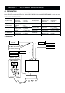
3-6 POWER SUPPLY CIRCUITS
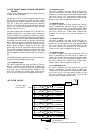
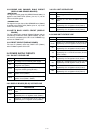
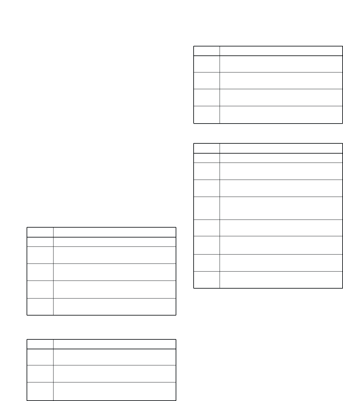
3-6-1 PA UNIT VOLTAGE LINE
LINE
HV13
HV
S13V
PA8V
PAT8
DESCRIPTION
The voltage from an external power supply.
The same voltage as the HV13 line passed
through the fuse (F6701).
The same voltage as the HV13 line passes
through the switching relay (RL6701).
8 V for transmitter circuits regulated by the +8
regulator circuit (IC6601).
8 V for transmitter circuits regulated by the T8
regulator circuit (Q6601, Q6602).
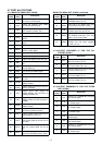
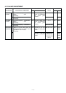
3-6-2 DISPLAY BOARD (RC-25) VOLTAGE LINE
LINE
HV13
10V
5V
DESCRIPTION
The voltage from PA and MAIN units via the
J8602.
Common 10 V converted from the 13 V line and
regulated by the +10 regulator circuit (IC8301).
Common 5 V converted from the 5 V line and
regulated by the +5 regulator circuit (IC8290).
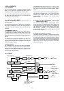
3-6-3 PLL UNIT VOLTAGE LINE
LINE
HV13
H5V
5V
8VL
DESCRIPTION
The voltage from PA and MAIN units via the
J5001.
Common 5 V line from the MAIN unit via the
J5071.
Common 5 V converted from the 13 V line and
regulated by the +5 regulator circuit (IC5001).
Common 8 V converted from the 13 V line and
regulated by the +8 regulator circuit (IC5031).
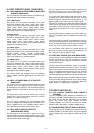
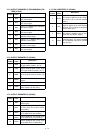
3-6-4 MAIN UNIT VOLTAGE LINE
LINE
S13V
R13V
8V
–5V
T8
R8
5V
H5V
DESCRIPTION
The voltage from the PA unit via the J1901.
Receive 13 V converted from the S13V line and
regulated by the R13 regulator circuit (IC1303).
Common 8 V converted from the 13 V line and
regulated by the +8 regulator circuit (IC1502).
Common –5 V converted from the 13 V line and
regulated by the –5 V DC-DC converter (IC1551,
D1551, D1552)
Transmit 8 V converted from the S13V line and
regulated by the T8 regulator circuit (Q1501).
Receive 8 V converted from the S13V line and
regulated by the R8 regulator circuit (Q1502).
Common 5 V converted from the 13 V line and
regulated by the +5 regulator circuit (IC1501).
Common 5 V converted from the 5 V line and
regulated by the +5 regulator circuit (IC3101).