


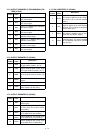
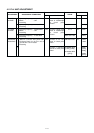
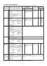
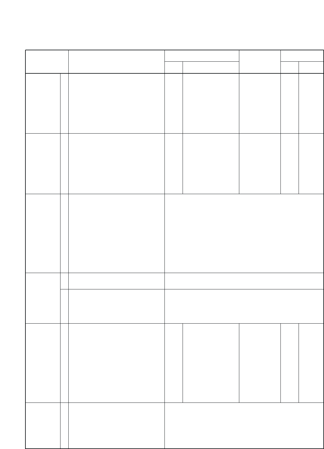
4-4 RECEIVER ADJUSTMENTS
”TOTAL GAIN”, “S-METER” and “DSC PEAK” adjustments must be performed at “ADJUSTMENT MODE”.
NOISE NULL
POINT
RECEIVER
GAIN
TOTAL GAIN
S-METER
DSC PEAK
([USA],[CAN]
only)
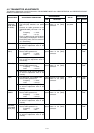
DSC SELF
CHECK
([USA],[CAN]
only)
1
1
1
1
2
1
1
• Operating frequency : 0.5 MHz
• Mode : H3E
• Preset L402 and L405 to max. clock-
wise.
• Preset L401, L403, L404 and L801 to
max. counter clockwise.
• Set the standard signal generator to
OFF (no signal output).
• Receiving
• Operating frequency : 12.2310 MHz
• Mode : J3E
• Connect a standard signal generator
to the [ANT] connector and set as:
Frequency : 12.2310 MHz
Level : 0.5 µV*
(–113 dBm)
Modulation : OFF
• Receiving
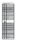
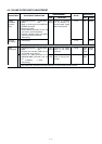
• While pushing HM-135’s “DOWN” key,
[TX] and [RX] switches, then turn
power ON.
• Push [2] swtich to enter the RX adjust-
ment mode.
• Connect a standard signal generator
to the [ANT] connector and set as:
Frequency : 12.3540 MHz
Level : 320 µV*
(–57 dBm)
Modulation : OFF
• Receiving
• Set the standard signal generator to
OFF (no signal output).
• Set the standard signal generator as:
Frequency : 12.3540 MHz
Level : 10 mV*
(–27 dBm)
• Receiving
• Push [3] switch to enter the DSC
adjustment mode.
LCD displayed :“DSC ADJUSTMENT”.
• DSC frequency : 8.4145 MHz
• Connect a standard signal generator
to the [DSC ANT] connector and set
as:
Frequency : 8.4145 MHz
Level : 0.5 µV*
(–113 dBm)
Modulation : OFF
• Receiving
• LCD displayed :”DSC SELF CHECK”
• DSC frequency : 8.4145 MHz
• Connect an RF power meter to the
[DSC ANT] connector on the rear
panel.
• Receiving
Front
panel
Front
panel
Front
panel
Connect an AC milli-
voltmeter to the [SP]
jack with a 4 Ω dummy
load.
Connect an AC milli-
voltmeter to the [SP]
jack with a 4 Ω dummy
load.
Connect an AC milli-
voltmeter to the [SP]
jack with a 4 Ω dummy
load.
Minimum output
level
Maximum out-
put level
Maximum out-
put level
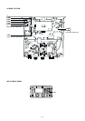
MAIN
MAIN
MAIN
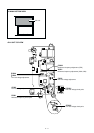
L207
L208,
L209,
L210,
L301,
L302,
L307
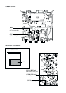
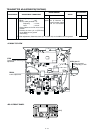
L2306,
L2307
ADJUSTMENT ADJUSTMENT CONDITIONS
UNIT LOCATION
VALUE
UNIT ADJUST
MEASUREMENT ADJUSTMENT
*The output level of the standard signal generator (SSG) is indicated as the SSG’s open circuit.
• Push the [ENT] switch to write the adjustment value in the mem-
ory.
• Push the [ENT] switch to write the adjustment value in the mem-
ory.
• Push the [ENT] switch to write the adjustment value in the mem-
ory.
4 - 7
• Push the [ENT] switch, and then verify to return to the “Main
menu” on the LCD display.
When this check is failure, displayed “NG” on LCD, and beep
sound.